


9000 Series 40 Part No. 1056953
Section 8 - Anti-tippers/Wheel Locks includes the following:
Installing/Adjusting the Anti-Tippers
Using/Adjusting the Patient Operated Wheel Locks
WARNING
After ANY adjustments, repair or service and BEFORE use, make sure all attach-
ing hardware is tightened securely - otherwise injury or damage may occur.
NOTE: The procedures in this section apply to NON-RECLINER models only EXCEPT where noted. For
9000XT RECLINER, refer to SECTION 9 of this manual.
INSTALLING/ADJUSTING THE ANTI-TIPPERS
WARNING
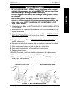
Anti-tippers are specific to the different seat-to-floor angles and/or seat-to-floor
heights. Refer to the chart in this section of the manual for correct usage and
adjustment. If these requirements CANNOT be achieved, DO NOT use the
wheelchair. Contact a qualified technician. If changing the seat-to-floor height
with or without a change to seat-to-floor angle, the correct anti-tippers MUST be
used to maintain a 1-1/2 to 2-inch ground clearance.
Seat-to-floor angle of 0°
or 3°: If so equipped, anti-tippers MUST be attached at all
times. Inasmuch as the anti-tippers are an option for 0°
or 3°
on this wheelchair
(You may order with or without the anti-tippers), Invacare strongly recommends
ordering the anti-tippers as a safeguard for the wheelchair user.
Seat-to-floor angle of 6°: If changing the seat-to-floor angle to 6°, anti-tippers
MUST be ordered and installed.
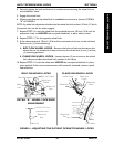
Anti-tippers MUST be fully engaged and release buttons fully protruding out of
adjustment holes.
Ensure both anti-tippers are adjusted to the same mounting hole.
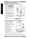
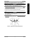
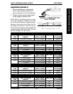
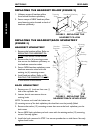
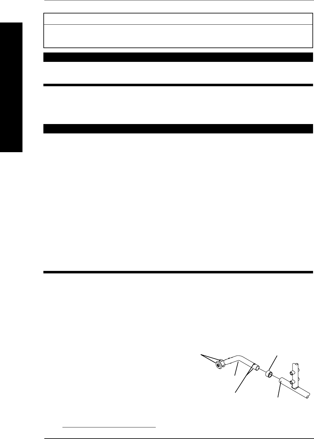
INSTALLING ANTI-TIPPERS (FIGURE 1)
1. Remove plug button (not shown) from end of rear frame tubing and install anti-rattles if not
already installed.
2. Press the release buttons IN and insert the anti-tippers with the anti-tipper wheels pointing
toward the ground/floor into the rear frame tubing until the bottom release button locks in
place.
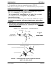
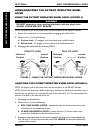
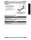
3. Measure the distance between the bottom
of the anti-tipper wheels and the ground/
floor.
NOTE: A 1-1/2 to 2-inch clearance between the bot-
tom of the anti-tipper wheels and the ground/floor
MUST be maintained at all times.
4. If the distance between the bottom of anti-
tipper wheels and the ground/floor is not
1-1/2 to 2-inches, adjust anti-tippers. Refer
to ADJUSTING THE ANTI-TIPPERS in this
section of the manual.
ANTI-TIPPERS/WHEEL LOCKSSECTION 8
ANTI-TIPPERS/WHEEL LOCKS
FIGURE 1 - INSTALLING THE
ANTI-TIPPERS
Anti-Tipper
Release Buttons
Rear Frame Tubing
Anti-Tipper Wheels
Anti-Rattle