


Page 9
Basic Maintenance
Warning
To avoid shock, remove the test leads and any input signals before opening
the case or replacing the battery or fuses.
Opening the Meter Case
Caution
To avoid unintentional short circuit, always place the uncovered Meter
assembly on a protective surface. When the case of the Meter is open, circuit
connections are exposed.
To open the Meter case, refer to Figure 1 and do the following:
1. Disconnect test leads from any live source, turn the rotary switch to OFF, and remove the
test leads from the front terminals.
2. Remove the battery door by using a Phillips-head screwdriver to remove the screw to the
battery door.
3. The case bottom is secured to the case top by three screws and two internal snaps
(at the LCD end). Use a Phillips-head screwdriver to remove the three screws.
4. Un-snap the Battery and table the battery snap out of the battery room.
Note
The gasket between the two case halves is sealed to, and must remain with, the case bottom. The case top lifts
away from the gasket easily. Do not damage the gasket or attempt to separate the case bottom from the gasket.
5. Hold the Meter display side up.
6. Lifting up on the input terminal end, disengage the case top from the gasket.
7. Gently unsnap the case top at the display end.
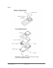
Battery Replacement (refer to Figure 1)
1. Disconnect the test leads from any circuit under test and turn off meter.
2. Remove the test leads from meter.
3. Loosen the screw from the battery cover on bottom case.
4. Remove battery cover.
5. Install a new battery after removing the original one.
6. Assemble battery cover onto bottom case with screwdriver and the screw
described in step 3.
Testing Fuses (FS1 and FS2)
To test the internal fuses of the Meter, refer to Figure 1 and do the following:
1. Turn the rotary selector switch to the mA position for 1A fuse test FS1 or A
position for 15A fuse test FS2.
2. To test FS1, plug a test lead into mA input terminal, and turn the rotary selector to the
mA position.
2.1 Fuse is OK if display shows normal functional graphics.
2.2 Fuse is defective if “FUSE” is displayed, and the built-in beeper alarms.
3. To test FS2, plug a test lead into A input terminal, and turn the rotary selector to the
A position.
3.1 Fuse is OK if the display shows normal functional graphics
3.2 Fuse is defective if “FUSE” is displayed, and the built-in beeper alarms.
Form Number TM61633-5 Rev 5 Dec 2006