


Page 15
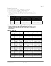
Testing the Resistance Function
To verify the accuracy of the resistance function, do the following:
1. Connect the Calibrator to VΩ and COM on the Meter.
2. Turn the rotary switch to Ω
3. Apply the inputs for step 1-7 in Table 5.
*Set reference if using a Multifunction Calibrator with diff or zero mode for steps 1, 2, and 3.
Compare the Meter display readings to the display readings in Table 5 step 1-7.
4. If the display reading falls outside of the range shown in Table 5, the meter does not
meet specification.
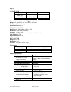
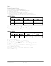
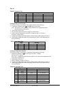
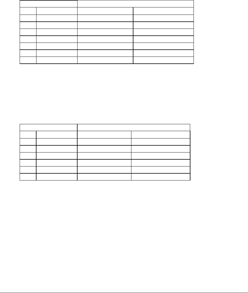
Table 5. Ω Test
Input
Readings
Step
Resistance Ω
61-633 61-635
1 0.00 00.00 to 00.02 00.00 to 00.02
2 360.00 358.00 to 362.00 358.72 to 361.28
3 3.6000K 3.5800 to 3.6200 3.5872 to 3.6128
4 36.000K 35.800 to 36.200 35.872 to 36.128
5 360.00K 358.00 to 362.00 358.72 to 361.28
6 3.6000M 3.5780 to 3.6220 3.5852 to 3.6148
7 36.000M 34.150 to 37.850 34.150 to 37.850
5. Press the blue button on the meter to toggle to LVΩ function.
6. Apply the inputs for step 1-6 in Table 6.
*Set reference if using a Multifunction Calibrator with diff or zero mode for steps 1 & 2.
Compare the Meter display readings to the display readings in Table 6.
7. If the display reading falls outside of the reading shown in Table 6, the meter does not
meet specification.
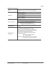
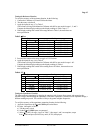
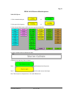
Table 6. LV Ω
Input Readings
Step
Resistance Ω
61-633 61-635
1 0.00 00.00 to 00.02 00.00 to 00.02
2 3.6000K 3.5620 to 3.6380 3.5764 to 3.6236
3 36.000K 35.620 to 36.380 35.764 to 36.230
4 360.00K 356.20 to 363.80 357.64 to 362.36
5 3.6000M 3.5600 to 3.6400 3.5744 to 3.6256
6 36.000M 33.430 to 38.570 33.430 to 38.570
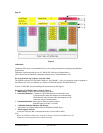
Testing the Capacitance Function
The Meter measures capacitance by charging the capacitor with a known direct current, and measuring the
resultant voltage, and calculating the capacitance. If the same capacitance is measured on an impedance bridge, a
different reading may result. This variance is likely to be greater at higher frequencies.
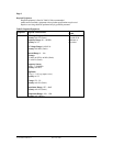
To verify the accuracy of the capacitance measuring function, do the following:
1. Apply the Capacitor to the VΩ and COM inputs on the Meter.
2. For steps 1 through 8 in Table 7.
a) Turn the rotary switch
b) Set the VΩ and COM inputs un-connected
c) Select Δ or (REL) for steps 1 and 2 in Table 7. After steps 1 and 2 are complete, escape
from Δ mode and press (RANGE) key until (AUTO) is displayed.
Form Number TM61633-5 Rev 5 Dec 2006