


10
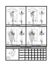
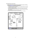
3.4.4 Lug Mounted ER2080S and ER2100L-LG – To maintain proper balance when the hoist is not loaded,
it is necessary to install a stabilizing shaft to prevent the hoist from pivoting on the main support shaft.
Refer to Figure 2-1 and Figure 2-2 for the size and location of the main support and stablizing holes in
the hoist’s top suspension plates.
3.4.5
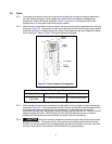
WARNING
Ensure that the fixed suspension point rests on the center of the hook’s saddle and
that the hook’s latch is engaged.
3.5 Electrical Connections
3.5.1
CAUTION
Ensure that the voltage of the electric power supply is proper for the hoist or trolley.
3.5.2
CAUTION
Do NOT apply electronic soft-start control or voltage varying controls to the ER2 or
NER2 hoist. Use of such devices may cause the motor brake and other electrical components to
malfunction. Variable frequency drives MAY be used with the single speed ER2/NER2 hoists, contact
Harrington Hoists, Inc. for more information.
3.5.3
DANGER
Before proceeding, ensure that the electrical supply for the hoist or trolley has
been de-energized (disconnected). Lock out and tag out in accordance with ANSI Z244.1 “Personnel
Protection -Lockout/Tagout of Energy Sources”.
3.5.4
DANGER
To avoid a shock hazard, DO NOT perform ANY mechanical or electrical
maintenance on the dual speed ( VFD control) trolley or hoist within 5 minutes of de-energizing
(disconnecting) the trolley or hoist. This time allows the internal VFD capacitor to safely discharge.
3.5.5
DANGER
Do NOT remove power to the dual speed (VFD control) hoist or trolley during
operation.
3.5.6
CAUTION
All dual speed hoists are equiped with a VFD. The VFD is used to control the high
and low lifting speeds. The speeds come preset from the factory (See Table 3-6, ER2OM). Speed
(frequency) can be customized. Refer to Section 3.6.10 of ER2OM, for hoist specific speed ranges and
instructions.
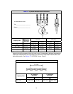
3.5.7 The following instructions apply when the hoist is hook mounted to a fixed suspension point or installed
on a manual trolley. The hoist is controlled by a pendant with two push buttons – one for lifting and one
for lowering. Refer to the appropriate trolley Owner’s Manual if the hoist is installed on a motorized
trolley. Special wiring considerations must be taken if the trolley is used with a trolley other than an
MR2 model.
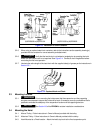
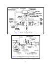
Pendant Cord
The Pendant Cord connects to the hoist via an 8-pin (8P) Plug and Socket. Make this connection
as follows:
Refer to Figure 3-5 or 3-6 depending on the Product Code.
For ER2080S and ER2100L - Insert the 8P Plug into the 8P Socket on the hoist body and
hand tighten the Lock Ring. Install the strain relief cable to the bottom of the hoist body.
For ER2100S, ER2150S and ER2200S - Insert the 8P Plug into the 8P Socket on the switch
box and hand tighten the Lock Ring. Install the strain relief cable onto the cord strain relief
stopper located at the 8P socket.