


Page 5SKU 93033 For technical questions, please call 1-800-444-3353.
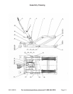
Assembly (continued)
Mounting the Lifting Frame into position.
1. Position the Stop Bar (3) and Lifting Frame (2) as shown in the Assembly Drawing, so
that the holes on the arms of both the Stop Bar (3) and Lifting Frame (2) line up with
the holes on the welded tabs on the Rear
Lift Arms (4). Place Pins (28) through the
Lifting Frame (2), the Tabs, Bushings (32), and Stop Bar (3).
Please note: The Bushings fit around the Bolts and inside the Stop Bar.
Installing the Pedal, Spring, and Handle.
1. Loosen and remove the screw that holds in the Foot Pedal (24). Insert the Foot Pedal
(24) into the receiver of the Jack (36). Use the screw you loosened from the pedal
assembly to secure the Foot Pedal (24) into the receiver of the Jack.
2. Insert the Handle (1) into the receptacle on the Lifting Frame (2) and secure it with the
Bolt (27).
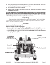
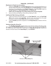
Testing the Stop Bar (33 and 35).
The Stop Bar (33 and 35) must be locked in one of the four positions after lifting a load.
Not engaging the Stop Bar (33 and 35) may result in serious injury or death, and damage the
Lift. Before each use, check that the lower tips of the Stop Bar (33 and 35) fit behind the
notches on the both sides of the Frame Base (11). See FIGURE 2.
FIGURE 2
Lower tip of the Stop
Bar (33 and 35)
Notches on Frame Base (11)
2. Secure the Bolts with Washers (29 and 30) and Spring Pin (38).