


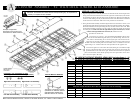
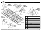
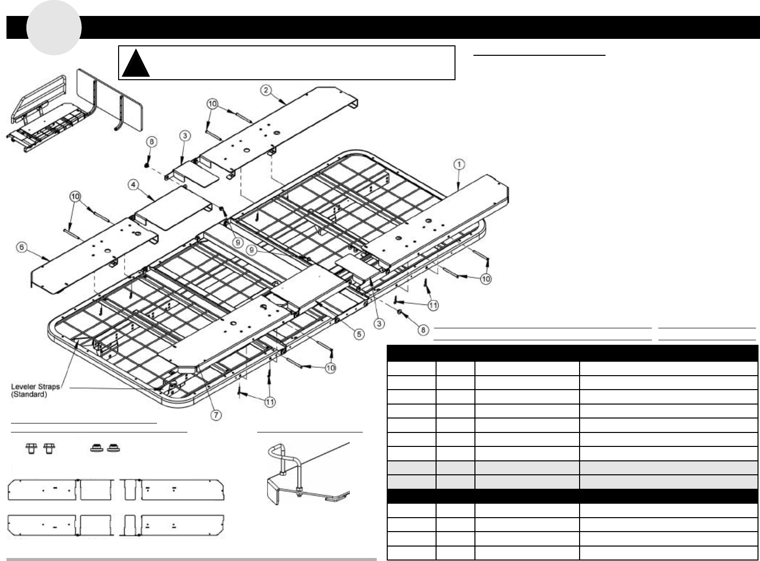
ccessory Assembly - 42” wide deck (order Kit# ZA811000)
A
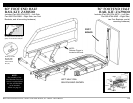
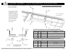
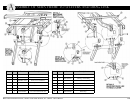
1. Align the right-hand foot assembly above the foot and knee decks with the angle hooks
facing downward and toward the foot end. The right knee extension (#4) hook should
be positioned just above the knee deck (toward the head end). Place the assembly flat
on the two decks making sure they are flush with the decks’ sides. Slide the foot extension’s
hooks onto the foot-end decks. Follow the same procedure for the left side.
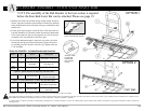
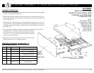
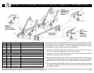
2. The right-hand head assembly should be aligned above the head-deck as shown, with
the angle hook positioned downward and just above the head deck. Place the assembly
flat on the head deck and seat pan making sure they are flush with the deck’s side. Slide
the extension assembly toward the foot end to lock the extension’s hooks onto the head
deck and pan seat. $-(463(5+$55+(3,*+5+$0'4($52$0(95(04,10,4105+(
1654,'(1)5+(3,*+5+$0'-0(((95(04,10. Follow the same
procedure for the left side.
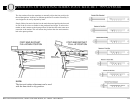
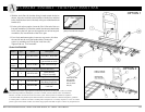
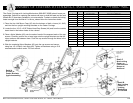
3. Locate the two 5/16-18 x .375” Hex Washer Head Machine Screws (#9)
and the two Self-Wrenching Nuts (#8) in your hardware bag. From the out-
side, insert a self-wrenching nut so that the square part of the nut fits into the
square hole of the head assembly mounting arm and the end extends through
the hole in the foot mounting arm. From the inside, screw in a machine screw and
tighten using a 1/2” wrench. Follow the same procedure for the opposite side.
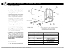
4. Locate the eight 5/16 x 3.50” Clevis Pins (#10) and eight 1-9/16 Hair Pin Clips
(#11) in your hardware bag. From the outside, insert the clevis pins through the
pre-drilled holes in the sides of the right- and left-hand head and foot expansion
pans. From the inside, insert the hair pin clips into the exposed holes on the clevis
pins to secure the pins to all decks.
*96#2EC:I6IA2?D:@?<:EFD6D
DA64:2=3@=E@?>2EEC6DDC6E2:?6CD
%((N!*
7@CEH@C6E2:?6CD
I2>A=6@7(:89E):56
IA2?D:@?&2?DH:E9@@E6?5
DD:DE6G:46-:56@@E3@2C5
@@E6?5
2=7(2:=
-:56
@@E3@2C5
#249:?6)4C6HD
"312<#3./88<;;/6,5A "312</+.88<;;/6,5A
##)#$"%$ #
/0<#3./88<;;/6,5A /0<#3.//+.;;/6,5A
)6=7-C6?49:?8$FED
!+-4+1/.3708=:+;;/6,53/;08:/+;A
+;;/6,5A43<37-5=./;+5568=7<3712+:.?+:/ '3./3<+<<:/;;"/<+37/:;
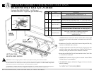
-($$*@C65F46E96C:D<@76?EC2A>6?E:E:D9:89=JC64@>>6?565E@:?4=F563@E9
H:5696257@@E3@2C5D2?52DD:DE56G:46DH96?AFC492D:?82?JM6IA2?D:@?<:E
G2C:6EJ@74@>A=6E6<:ED2C62G2:=23=6
!
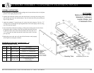
Item # Qty. Part # Description
1 1 999-0811-921G Left-Hand Head Extension Weldment
2 1 999-0811-922G Right-Hand Head Extension Weldment
3 2 999-0811-004G & 005G Left- & Right-Hand Seat Pan Extension
4 1 999-0810-012G Right-Hand Knee Extension
5 1 999-0810-002G Left-Hand Knee Extension
6 1 999-0811-932G 80” Right-Hand Foot Extension Weldment
7 1 999-0811-931G 80” Left-Hand Foot Extension Weldment
Not Shown 1 999-0846-932G Opt. 76” Right-Hand Foot Extension Weldment
Not Shown 1 999-0846-931G Opt. 76” Left-Hand Foot Extension Weldment
@E9!:ED?4=F562C5H2C6@IH9:4992DE967@==@H:?8
8 6 999-0032-010 Self-Wrenching Nut (4 pre-assembled on decks)
9 6 100-5431-002
5/16-18 x .375” HWHMS
(4 pre-assembled on decks)
10 8 100-7931-008 5/16 x 3.50” Clevis Pin w/Hole
11 8 100-2001-006 1-9/16 Hair Pin Clip
B'$'$ %$ "#* 7-5=./;</6;
B'$'$ %$ "#* 7-5=./;</6;
&2D:4>6C:42?#65:42=&C@5F4ED25:G:D:@?@762=E9&C@5F4ED?4K#2EC:IK(,#2?F2=