


Installation
6 Installation and Operation
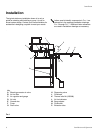
Installation
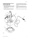
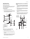
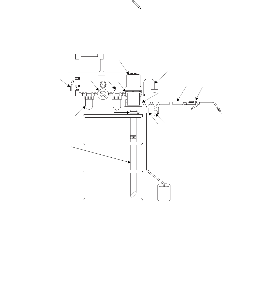
The typical stationary installation shown in is only a
guide for selecting and installing a pump; it is not an
actual system design. Contact your Graco distributor for
assistance in designing a system to meet your needs.
.
Letters used to identify components in FIG. 1 are
referred to in the package installation drawings,
F
IG. 3 through FIG. 7. Additional letter references
are used in installation drawings as necessary.
A
B
C
D
E
F
G
H
L
J
K
M
Key
A Bleed-type master air valve
B Air line filter
C Air regulator and gauge
D Air inlet
E Ground wire
F Pump
G Drain valve
H Dispensing valve
J Fluid hose
K Thermal relief kit (235998)
L Air line lubricator
M Bung adapter
N Fluid outlet
P Extension tube
N
P
FIG. 1