


Digital Multimeters
Performance Tests
7
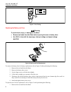
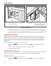
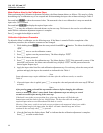
2. Remove the Meter from its holster.
3. Remove two screws from the case bottom.
4. Separate the case bottom from the case top.
5. Remove the fuse from its holder and replace with an 11 A, 1000 V, FAST fuse having a minimum
interrupt rating of 17,000 A. Use only Fluke PN 803293.
6. To re-assemble the Meter, attach the case bottom to the case top and secure with the two screws. Insert
the Meter into its holster.
Cleaning the Meter
Wipe the case with a damp cloth and mild detergent. Do not use abrasives or solvents. Dirt or moisture in the
terminals can affect readings.
Performance Tests
XWWarning
To avoid electric shock, do not perform the performance test procedures unless
the Meter is fully assembled.
The following performance tests verify the complete operation of the Meter and check the accuracy of each Meter
function against its specifications. The recommended calibration interval is 12 months. If the Meter fails any part of
the test, calibration adjustment and/or repair is indicated.
In the performance tests, the Meter is referred to as the unit under test (UUT).
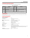
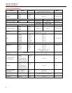
Required Equipment
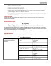
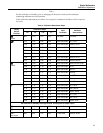
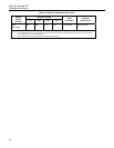
Table 2 lists the equipment required to conduct a performance test on the Meter.
Table 2. Required Equipment
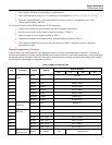
Recommended Equipment Measurement Function Accuracy
DC Volts 10 mV to 600 V
±0.125 %
DC Current (115, 116, and 117) 600 μA to 10 A
±0.25 %
AC Volts 6 mV to 600 V
±0.25 % @ 45 Hz to 1 kHz
AC Current (115, 116, and 117) 600 μA to 10 A
±0.375 % @ 45 Hz to 1 kHz
Resistance 0 to 5 MΩ
±0.225 %
10 to 30 MΩ
±0.375 %
Capacitance (115, 116, and 117) 9 to 900 μF
±0.475 %
5500A Multi-product Calibrator (or
equivalent)
Temperature (116) 0 °C to 400 °C ±0.25 %