


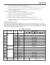


Digital Multimeters
Calibration Adjustment
15
Notes
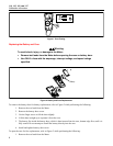
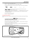
Set the calibrator to Standby prior to changing the function switch position and after
completing adjustment of each function.
If the calibration adjustment procedure is not properly completed, the Meter will not operate
correctly.
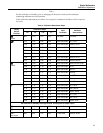
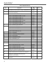
Table 4. Calibration Adjustment Steps
Calibration Steps
Rotary
Switch
Position
114 115
[1]
116
[1]
117
[1,2]
Input
Terminals
Calibrator
Source Value
e
Ohms
N/A C/01 C/01 C/01
[2]
No leads No leads
C/01 C/02 C/02 C/02 VΩ/+ and COM 0 V, 0 Hz
C/02 C/03 C/03 C/03 VΩ/+ and COM 300 mV, 0 Hz
C/03 C/04 C/04 C/04 VΩ/+ and COM 100 mV, 0 Hz
C/04 C/05 C/05 C/05 VΩ/+ and COM -300 mV, 0 Hz
C/05 C/06 C/06 C/06 VΩ/+ and COM 60 mV, 0 Hz
C/06 C/07 C/07 C/07 VΩ/+ and COM 600 mV, 0 Hz
m
C/07 C/08 C/08 C/08 VΩ/+ and COM 600 mV, 60 Hz
C/08 C/09 C/09 C/09 VΩ/+ and COM 600 e, 2-wire comp
C/09 C/10 C/10 C/10 VΩ/+ and COM 6 ke
C/10 C/11 C/11 C/11 VΩ/+ and COM 60 ke
C/11 C/12 C/12 C/12 VΩ/+ and COM 600 ke
C/12 C/13 C/13 C/13 VΩ/+ and COM 6 Me
[3]
C/13 C/14 C/14 C/14 VΩ/+ and COM Short
[3]
e
Ohms
C/14 C/15 C/15 C/15 VΩ/+ and COM 40 Me
[3]
C/15 C/16 C/16 C/16 VΩ/+ and COM 6 V, 60 Hz
C/16 C/17 C/17 C/17 VΩ/+ and COM 60 V, 60 Hz
C/17 C/18 C/18 C/18 VΩ/+ and COM 600 V, 60 Hz
C/18 C/19 C/19 C/19 VΩ/+ and COM 6 V, 0 Hz
C/19 C/20 C/20 C/20 VΩ/+ and COM 60 V, 0 Hz
K
C/20 C/21 C/21 C/21 VΩ/+ and COM 600 V, 0 Hz
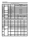
Set calibrator to standby, reconfigure leads, and program for amps output.
? N/A C/22 N/A C/22 A and COM 6 A, 60 Hz
[3]
A N/A C/23 N/A C/23 A and COM 6 A, 0 Hz
$
AC μamps
N/A N/A C/22 N/A + and COM 600 μA, 60 Hz