


X K 3 1 9 0 - A 1
+P
15 In calibration or parameters setting mode, pressing [weigh], it will exit from original
calibration or setting mode and return to weighing mode.
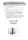
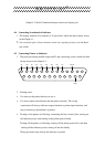
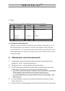
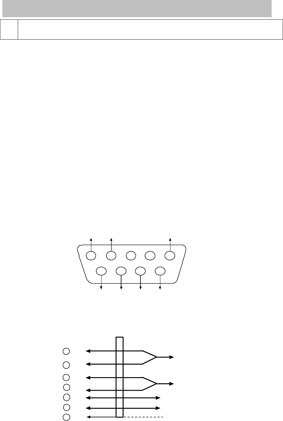
2.3 Connecting Loadcell to Indicator
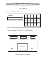
1. The 9-pin socket is used for the link-up of loadcell, which has been clearly shown
in the graph 2-3.
2. The 4-pin shielded cable is used, +S must be short connected with +E, -S and -E. The
indicator does not have the function of long distance compensation.
3. ▲ !Indicator must be reliably connect ed to Loadcell and shielded-cable of
loadcell must be reliably connect ed to underground . If indicator is
powered on, the user should not insert or withdraw the plug in order to
protect the indicator and loadcell.
4. ▲ !Sensor and indicator are static sensitive devices; you must adopt anti-static
measures. In order to protect the operator ,indicator, and relevant devices,
you should install lightning rod in the thunderstorm frenquently
happening area.
1
23
45
6
7
8
9
-E
-S
Shield
+E
+S
-IN +IN
5 Shield
8 -IN
9 +IN
1 -E
2 -S
7 +S
6 +E
+
_
Terminal of Indicator Terminal of Sensor
Bridge of Power Supply
Signal Output
(Graph 3-2 ) Connection of the load cell