


X K 3 1 9 0 - A 1
+P
communication mode parameters.
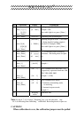
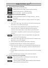
(2) The sequence of parameters setting as following:
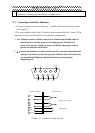
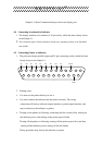
Connecting the loadcell , the indicator enters into working mode which is shown in
the Graph 2-3.
Insert the setting jumper into 15-pin socket at the back of indicator. (There is a 15-pin
plug in the packing carton with its 14-pin shorte connected with 15-pin. ).
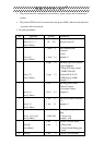
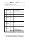
Setup communication parameters as following:
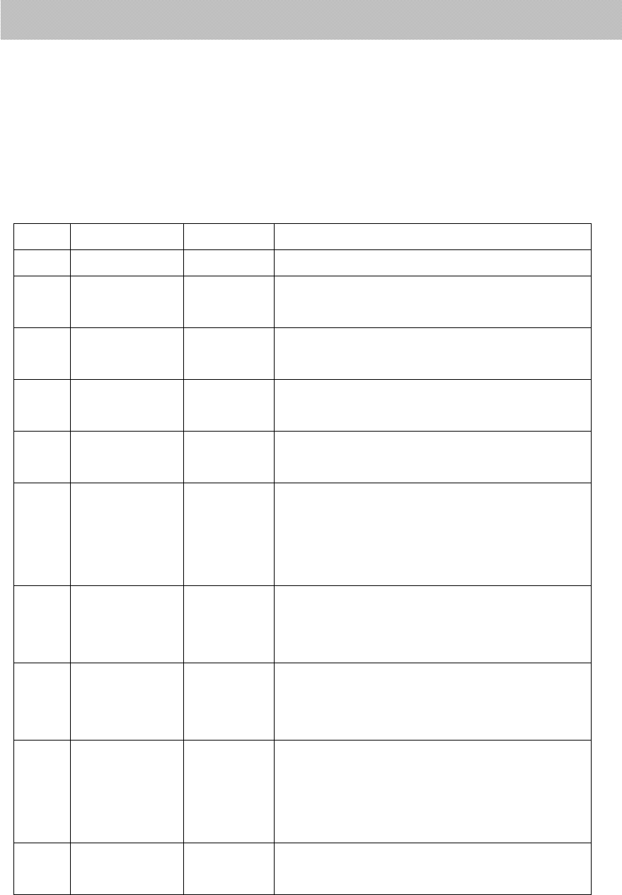
Step Operation Display Explanation
1 Press[CALB] Plug in calibration jumper
2
Press[Enter]
[E **]
Don’t change this data and enter next step.
3
Press[Enter]
[dc **] Don’t change this data and enter next step.
4
Press[Enter]
[Pon **] Don’t change this data and enter next step.
5
Press[Enter]
[F
******]
Don’t change this data and enter next step.
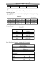
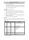
6
Press[Enter]
Press[Enter]
[H *****]
[L *****]
[td **.**]
Don’t change this data and enter next step.
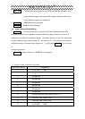
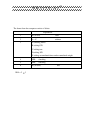
7
Press[1]
Press[Enter]
[A d r **]
[A d r01 ]
Communication address (01~26)
Example: 1
8
Press[1]
Press[Enter]
[bt *]
[bt 1]
Baud rate of serial communication (0~4)
which represent baud rate of
600,1200,2400,4800,9600
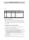
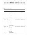
9
Press[0]
Press[Enter]
[tF *]
[tF 0]
Serial communication mode:
0- Continous transmitting mode,
unreceiving
1- command responding mode
10 Weighing
mode
End of communication parameters setting
( Please note the explanation. Don’t change other parameters setting carelessly )
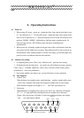
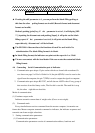
4.7 Date, Time Set-up
(1) Under weighing status of the indicator, press [ Date ] key, and date sign lamp is
lighted. Indicator display original data at this time. If it is correct, then press