


February 2015
10
Quick Start Guide
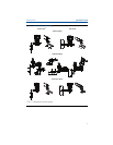
3. Ground housing to fulfill local grounding regulations.
4. Ensure proper grounding. It is important that the instrument cable shield:
a. Be trimmed close and insulated from touching the transmitter housing
b. Be connected to the next shield if cable is routed through a junction box
c. Be connected to a good earth ground at the power supply end
5. If transient protection is needed, refer to section “Grounding for Transient
Terminal Block” for grounding instructions.
6. Plug and seal unused conduit connections.
7. Replace the housing cover.
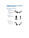
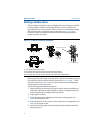
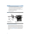
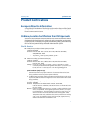
Figure 7. Wiring
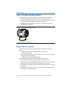
Grounding for transient terminal block
Ground termination is provided on the outside of the electronics housing and
inside the terminal compartment. These grounds are used when the transient
protection terminal blocks are installed. It is recommended that 18 AWG or larger
wire is used to connect housing ground to earth ground (internal or external).
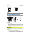
If the transmitter is currently not wired for power up and communication, follow
procedures 1-7 of Connect the wiring and power up
. When the transmitter is
properly wired, refer to Figure 7 for internal and external transient grounding
locations.
A. Minimize Distance
B. Trim shield and insulate
C. Protective Grounding Terminal
D. Insulate Shield
E. Minimize Distance
F. Connect Shield Back to the Power Supply
Ground
DP
A
B
C
E
D
F