


Instruction Manual
IM-106-880, Rev 1.0
January 2007
OCX 8800
http://www.raihome.com
Index
A
Accessories . . . . . . . . . . . . . . 1-12
Alarm Relay Events . . . . . . . . 7-11
Assemble O2 Sensor . . . . . . . 6-16
Autocalibration Setup, HART . . 5-1
Autocalibration, HART . . . . . . . 5-3
B
Band Heater Height . . . . . . . . 6-19
Blowback System . . . . . . 1-5, 2-13
Blowback with Autocalibration 2-14
Blowback without Autocalibration 2-15
C
Cell Output . . . . . . . . . . . . . . . . 7-7
COe Band Heater . . . . . . . . . . 6-11
COe Sensor Assembly 6-8, 6-14, 6-15,
. . . . . . . . . . . . . . . . . . . . . . . 6-19
COe Sensor Holder Alignment 6-20
COe Sensor Parts . . . . . . . . . . 6-18
COe Sensor, Thermocouple, and Heat-
er Connections . . . . . . . . . . . 6-21
Combustibles Sensor . . . . . . . . 1-3
Component Checklist . . . . . . . . 1-1
Configuration . . . . . . . . . . . . . . 3-2
D
D/A Trim Procedure . . . . . . . . . 5-8
Defaults . . . . . . . . . . . . . . . . . . . 3-3
Diagnostic Alarms . . . . . . . . . . . 7-2
E
Eductor . . . . . . . . . . . . . .6-11, 6-17
Eductor Holder . . . . . . . . . . . . 6-11
Electrical Noise . . . . . . . . . . . . . 7-1
Electronics Housing Components 8-6
Electronics Housing Disassembly 6-25
Electronics Housing Terminal Blocks
6-3
Electrostatic Discharge . . . . . . . 7-1
Essential Instructions . . . . . . . . . . i
F
Factory Repair . . . . . . . . . . . . .C-1
Fault Indications . . . . . . . . . . . . 7-3
Fault Isolation . . . . . . . . . . . . . .7-3
Fitting, ‘E’ Type . . . . . . . . . . . . 6-31
Fitting, ‘R’ Type . . . . . . . . . . . .6-31
Fuse Locations . . . . . . . . . . . . . 7-2
G
Grounding . . . . . . . . . . . . . . . . . 7-1
H
Handling . . . . . . . . . . . . . . . . . . 1-6
HART Communicator . . . . . . . . 4-1
HART Connections . . . . . . . . . . 1-7
HART PC Connections . . . . . . . 4-4
HART Signal Connections . . . . . 4-1
HART Signal Line Connections 4-2,
4-3
Heater Strut Assembly . . . . . . 6-16
I
Install Eductor . . . . . . . . . . . . . 6-17
Install Electronics Stack . . . . . . 6-28
Install Flash PROM . . . . . . . . . 6-28
Install Integral OCX 8800 . . . . . 6-4
Install Solenoid Valves . . . . . . 6-28
Install Tube Fittings . . . . . . . . .6-32
Instrument Air . . . . . . . . . . . . . . 1-7
M
Manual Calibration, HART 5-3, 5-5, 5-6
Material Safety Data Sheet . . .A-24
N
Nernst Equation . . . . . . . . . . . . 1-3
O
O2 Cell and Heater Strut 6-22, 6-24
O2 Cell and Heater Strut Assembly
6-6, . . . . . . . . . . . . .6-7, 6-13, 8-9
O2 Cell Output Voltage . . . . . . . 1-4
O2 Cell Replacement Kit . . . . . 6-13
O2 Cell, Heater, and Thermocouple
6-13
O2 Cell, Thermocouple, and Heater
Connections . . . . . . . . . 6-7, 6-23
OCX Specifications . . . . . . . . . .1-9
OCX with Integral Electronics . .6-2
Operation Diagram . . . . . . . . . .1-6
Oxygen and Cell Output . . . . . .7-7
P
Personal Computer (PC) . . . . . .1-5
Power Up . . . . . . . . . . . . . . . . . .3-3
Pre-Heater . . . . . . . . . . . . . . . .6-15
Pre-Heater Alignment . . . . . . .6-16
Product Matrix . . . . . . . . . . . . . 1-11
R
Reference Air Tube . . . . . . . . . .6-7
Removal and Installation . . . . . .6-1
Remove Eductor . . . . . . . . . . .6-11
Remove EEprom . . . . . . . . . . .6-25
Remove Electronics Stack . . . .6-26
Remove Flash PROM . . . . . . .6-25
Remove OCX 8800 . . . . . . . . . .6-2
Remove Solenoid Valves . . . . .6-27
Remove Tube Fittings . . . . . . .6-31
Repair Sensor Housing . . . . . . .6-5
Replace Tube Fittings . . . . . . .6-31
Reset Procedure . . . . . . . . . . . .3-4
Resistance Devices (RTD) . . . .1-3
Returning Material . . . . . . . . . . C-1
RTD . . . . . . . . . . . . . . . . . . . . . .1-3
S
Sample and Exhaust Tubes 6-12, 6-16
Sample Block Heater Rods 6-7, 6-22
Selected Distributed Control Systems
1-5
Sensor Housing Components 8-2, 8-4
Sensor Housing Disassembly . .6-5
Sensor Housing Leak Test . . . .6-24
Solenoid Power Terminals . . . .6-30
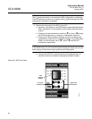
SPA Configuration Menu . . . . . B-6
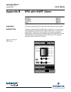
SPA Front Panel . . . . . . . . . . . B-4
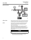
SPA Interface Connections . . . B-2
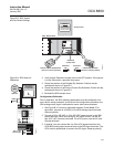
SPA Setup for Calibration . . . . B-3
SPA with HART Alarm . . . . . . . B-1
Specifications . . . . . . . . . . . . . . .1-9
SW1 . . . . . . . . . . . . . . . . . . . . . .3-2
SW2 . . . . . . . . . . . . . . . . . . . . . .3-2