


Metro Power III Owner’s Manual GF0600059RevB06, November 2006
13
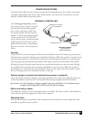
POWER DRIVE SYSTEM
e Metro Power III power drive system consists of two independent rear drive wheels, an integral
controller, independent, direct drive right and left motors, and two twelve volt batteries (not sup-
plied by Graham-Field) that provide power.
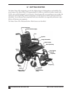
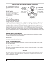
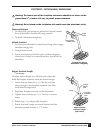
INTEGRAL CONTROLLER
e VSI Integral Controller contains
the joystick, battery charger receptacle
(also used for the optional program-
mer), motor and battery cables, and
the mounting holes for the extension
bracket, as well as those features found
on the control panel: e ON/OFF
switch, battery gauge, maximum speed/
profile indicator, horn button, speed/
profile decrease button, and speed/pro-
file increase button. eir descriptions
follow.
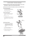
Joystick
e JOYSTICK controls the speed and direction of wheelchair travel. e further you push the joy-
stick from the rest position the faster your wheelchair will move. When the joystick is returned to the
neutral (center) position or released, the control system will bring the wheelchair to a smooth stop.
Upon stopping, electromechanical park brakes will engage to prevent the wheelchair from rolling.
Moving the joystick forward (away from the user) causes the wheelchair to move forward. Moving
the joystick back (toward the user) causes the wheelchair to travel in reverse. When the joystick is
moved right to 3 o’clock position, the wheelchair will turn to the right; when the joystick is moved
left to 9 o’clock position, the wheelchair will turn to the left.
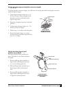
Battery charger receptacle (and optional programmer receptacle)
e receptacle for the battery charger / optional programmer is located on the underside of the con-
troller as specified in picture above. Use only the battery charger supplied with the wheelchair.
s
Caution: Use only the battery charger supplied with your wheelchair. Use of another battery
charger could damage the Controller and the battery charger.
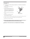
Motor and battery cables
e cables that connect to the left and right motors are labeled. e battery cable is either labeled or
color-coded to match the appropriate battery box connector.
Mounting holes
e holes that mount the controller to the controller extension bracket are on the underside of the
controller as specified in picture above.
POWER
battery box connector
battery charger/
programmer
receptacle
control panel
motor connector
joystick
mounting holes
VSI integral controller *
* VSI is a trademark of
PG Drives Technology, Inc.