


17
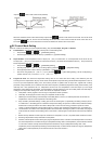
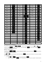
17 When HOLD status happens to PID program control, alarm output is ON.
18 When STOP status happens to PID program control, alarm output is ON.
19 When END status happens to PID program control, alarm output is ON.
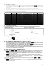
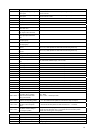
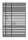
¾ To set Alarm Mode: Use the parameters , , in 【Initial Setting Mode】 to select the alarm mode. There are
in total of 19 different modes (as listed in the table above).
¾ To set Deviation Upper Limit of Alarm: Use the parameters
, , in 【Operation Mode】to set the deviation
upper limit.
¾ To set Deviation Lower Limit of Alarm: Use the parameters
, , in 【Operation Mode】 to set the deviation
lower limit.
¾ To set Alarm Delay Time(Unit: seconds): Use the parameters
, , in 【Initial Setting Mode】 to set the alarm
delay time.
¾ To set Reverse Alarm: Use the parameters
, , in【Initial Setting Mode】 to set the digit Y of value xxYx
(When Y=0: reverse, Y=1: forward)
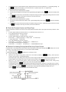
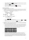
¾ To set Alarm 3: Alarm 3 function is available when an output board is connected to Output 2. Use the parameter
in【Initial
Setting Mode】, press the key ▲ or ▼ to select for the following control output items: H1H2, C1H2… H1A2(H defines heating, C
defines cooling, 1 indicates Output1, 2 indicates Output2 , A indicates Alarm3).
¾ Select x1A2( set x to H or C) to operates Alarm3. To set Standby Alarm: Use the parameters
, , in 【Initial
Setting Mode】 to set the digit Y of value xxxY (When Y=0: normal opeartion, Y=1: standby).
¾ To set Hold Alarm: Use the parameters
, , in【Initial Setting Mode】 to set the digit Y of value xYxx ( When
Y=0: normal operation, Y=1: Hold).
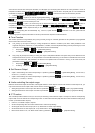
¾ To set Peak Alarm Signal: Use the parameters
, , in【Initial Setting Mode】 to set the digit Y of value Yxxx
(when Y=0: normal operation, Y=1: peak signal).
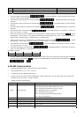
Note: Refer to the table
¾ PV Color Change Function: This controller provides PV color change function. The PV display color will be changed if the selected
alarm energized. Use the parameter
(PV color) in 【Initial Setting Mode】 to select the alarm, selectable items are ,
, , and .
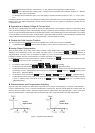
RS-485 Communication
1. Supporting transmission speed: 2,400, 4,800, 9,600, 19,200, 38,400bps
2. Non-supported formats: 7, N, 1 or 8, O, 2 or 8, E, 2
3. Communication protocol: Modbus (ASCII or RTU)
4. Function code: 03H to read the contents of register (Max. 8 words). 06H to write 1 (one) word into register. 02H to read the bits
data (Max.16 bits). 05H to write 1 (one) bit into register.
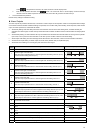
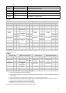
5. Address and Content of Data Register:
Address Content Definition
Measuring unit is 0.1, updated one time in 0.1 second
The following reading value display indicates error occurs:
8002H : Initial process (Temperature value is not got yet)
8003H : Temperature sensor is not connected
8004H : Temperature sensor input error
8006H : Cannot get temperature value, ADC input error
1000H Present value (PV)
8007H : Memory read/write error
1001H Set point (SV) Unit is 0.1, oC or oF
1002H Upper-limit of temperature range The data content should not be higher than the temperature range
1003H Lower-limit of temperature range The data content should not be lower than the temperature range
1004H
Input temperature sensor type
Please refer to the contents of the “Temperature Sensor Type and Temperature
Range” for detail
1005H Control method 0: PID, 1: ON/OFF, 2: manual tuning, 3: FUZZY
Bit3 Bit2 Bit1 Bit0
Peak Alarm Hold Alarm Reverse Alarm Standby Alarm