


13
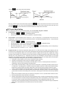
Auto Fine-tune the PID value. During the calculation, AT LED lights up in the display panel. When the PV value generates 2 curves of
temperature oscillation based on the SV value, the AT process is completed and the AT LED in the panel goes out. The calculated PID
parameters are displayed in
, , , and , of which their content can be revised by the user.
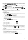
¾ Automatic switching-over Multiple PID sets:
Set parameter
to 0 (PID 0, the first set) in【Regulation Mode】, set the required SV value (e.g. 100 degree), set parameter
as ON; on completion of auto fine-tuning, the system fills in parameters =100, , , and
automatically, their content can be revised by the user.
Set parameter
to 1 (PID 1, the second set), set the required SV value (e.g. 150 degree), set parameter as ON; on
completion of auto fine-tuning, the system fills in parameters
=150, , , and automatically.
Set parameter
to AUTO, System will verify on its own whether the current SV value is closer to parameter or ,
and load the corresponding PID set automatically. E.g., if SV=110, system will load
parameters. If SV=140, system will load
parameters.
If more SV groups are required, PID2~PID5 can be set up with the same sequence as described above.
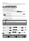
Tune Function
This machine provides 2 tuning methods (Auto_Tuning and Self_Tuning) for automatic generation of PID parameters (only applicable
when control mode is set to PID control).
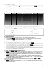
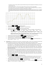
z Auto_Tuning: by full output of heating or cooling, temperature is allowed to oscillate up and down. Attain parameters of the
magnitude and period, calculate P, I, D, IOF parameters; in addition, save the temperature setting value for performing AT, for the
use of PID control. After Auto_Tuning, PID control will be carried out automatically.
¾ Set parameter
to in 【Initial Setting Mode】
¾ AT setting: Set parameter
to in 【Regulation Mode】
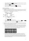
z Self_Tuning: By full output of heating or cooling, max. slope of temperature alteration and system delay can be attained from the
Temperature-Time Curve, and P, I, D, IOF parameters can be calculated. Self tuning can be carried out in RUN mode and in STOP
mode. In the RUN mode, PID parameters are allowed to be updated when the machine is running; in the STOP mode, PID
parameters for the SV value can be attained.
¾ Set parameter
to in【Initial Setting Mode】
¾ ST Setting: set parameter
to in 【Regulation Mode】
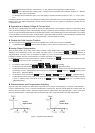
Set Reverse Output
¾ output 1 reverse setting: Set a value corresponding to Y position by parameter in 【Initial Setting Mode】, such as xxxY (Y
can be 0 or 1; 0: forward; 1: reverse)
¾ output 2 reverse setting: Set a value corresponding to Y position by parameter
in 【Initial Setting Mode】, such as xxYx (Y
can be 0 or 1; 0: forward; 1: reverse)
Limits controlling the output range
Maximum and minimum output can be limited; if the original maximum control output is 100% and the minimum control output is 0%, you
may set the maximum control output to 80% and the minimum control output to 20%.
¾ Setting the upper limit of control output: Set values for parameters
(output 1), (output 2) in【Operation Mode】.
¾ Setting the lower limit of control output: Set values for parameters
(output 1), (output 2) in【Operation Mode】.
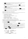
CT Function
This controller provides maximum 2 CTs (CT1 and CT2) for measuring current values of output 1 and output 2; when the corresponding
output is ON, use CT to measure the corresponding current. An alarm will be activated (ON) when the current exceeds the setting range
of alarm. (A hardware PCB is required.)
¾ Insert CT1, CT2 PCBs to Option1, Option2
¾ Set the corresponding alarm to CT Alarm: Please refer to “Alarm Output Setting”.
¾ Set the upper limit of CT alarm output (unit: 0.1A): Please refer to “Alarm Output Setting”.
¾ Set the lower limit of CT alarm output (unit: 0.1A): Please refer to “Alarm Output Setting”.
¾ Read current values of CT1, CT2: Read current values by parameters
, in 【Operation Mode】.