


Installation Instructions MCB1U / LCB1U
7
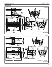
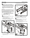
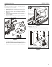
3. Install two 5/16" x 1" self-tapping screws (U) through two
5/16" flat washers (V), bottom stop collar (BB), and into
installed column.
4. Install and tighten 5/16" x 3/4" set screw (X) into bottom stop
collar (BB). (See Figure 3)
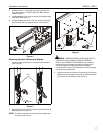
5. Install and tighten two 5/16" x 3/4" set screws (X) through
side of mount (DD) and against column. (See Figure 4)
Figure 4
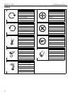
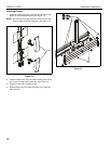
Attaching Interface Brackets to Display
1. Lower the latch mechanism on all interface brackets (FF).
(See Figure 5)
Figure 5
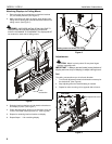
2. Align the center of the interface brackets (FF) with center of
both displays. (See Figure 6)
NOTE: The diamond-shape hole in the bracket corresponds to
the center of the mount.
Figure 6
WARNING: IMPROPER INSTALLATION CAN LEAD TO
DISPLAY FALLING CAUSING SERIOUS PERSONAL
INJURY OR DAMAGE TO EQUIPMENT! Using screws of
improper size may damage your display. Properly sized
screws will easily and completely thread into display
mounting holes. If spacers are required, be sure to use longer
screws of the same diameter.
3. Select correct screws, spacers (if necessary) and universal
washers from the hardware bag (A-N) and attach brackets
(FF) to back of both displays. (See Figure 6)
5
(X) x 2
(FF)
1
Latch
mechanism
Center of
bracket
(N)
(L or M)
(A-K)
(FF)
3
2