


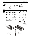

MCB1U / LCB1U Installation Instructions
6
INSTALLATION
WARNING: FAILURE TO PROVIDE ADEQUATE
STRUCTURAL STRENGTH FOR THIS COMPONENT CAN
RESULT IN SERIOUS PERSONAL INJURY OR DAMAGE
TO EQUIPMENT! It is the installer’s responsibility to make
sure the structure to which this component is attached can
support five times the combined weight of all equipment.
Reinforce the structure as required before installing the
component.
IMPORTANT ! :
These instructions assume that a 1-1/2"
NPT or NPSM following ANSI/ASME B1.20.1 (Schedule
40, 0.154" minimum thickness steel or aluminum-ASTM
B221) threaded extension column (not included); or a UL
Listed Chief CPA Series extension column (not included) -
- has been properly installed and is in place.
NOTE: Proceed to Attaching Mount to NPT Column section
or Attaching Mount to CPA Extension Column
section, as appropriate.
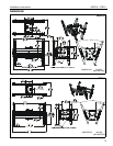
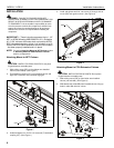
Attaching Mount to NPT Column
CAUTION: WATCH FOR PINCH POINTS! Do not place
fingers between moveable parts.
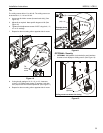
1. Slide ceiling mount (DD) up from below onto installed
column (not included). (See Figure 1)
2. Thread bottom coupling (CC) onto installed column until
tight, with a minimum of four threads engaged.
Figure 1
3. Install and tighten one 10-24 x 1/4" set screw (T) into bottom
coupling (CC). (See Figure 1)
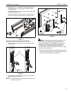
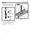
4. Install and tighten two 5/16" set screws (X) through side of
mount (DD) and against column. (See Figure 2)
Figure 2
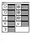
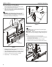
Attaching Mount to CPA Extension Column
CAUTION: WATCH FOR PINCH POINTS! Do not place
fingers between moveable parts.
1. Slide ceiling mount (DD) up from below onto installed
column (not included). (See Figure 3)
2. Slide bottom stop collar (BB) onto installed column, lining up
holes in collar with holes in column.
Figure 3
1
2
2
3
(T) x 1
(CC)
(DD)
4
(X) x 2
(DD)
1
(DD)
2
4
3
(U) x 2
(V x 2)
(BB)
(X) x 1