


Page 6 of 8 HPK-150 Installation and Operating Instructions
02/05/10 CP5061A
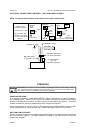
ELECTRICAL CONNECTIONS CONTINUED (NOT USING SWITCH PANEL)
NOTE: Permanent disconnection of the vehicle horn is NOT recommended.
OPERATION
USING SWITCH PANEL
In an emergency situation, set the HORN SELECT switch to AIR and turn on the LITE switch in
one sweeping motion. When the horn ring on the vehicle is pressed the amplifier and speaker
produce a simulated air horn sound. A power indicator on the amplifier also lights up. The power
indicator is located on the same surface where wires emerge from amplifier.
When the emergency is over, turn off the LITE switch and set the HORN SELECT switch to VEH
in one sweeping motion. When the horn ring is pressed the regular vehicle horn will sound.
NOT USING SWITCH PANEL
As soon as power is applied, the amplifier and speaker produce a simulated air horn sound and
the power indicator lights up. The power indicator is located on the same surface where wires
emerge from amplifier.
Sound Hazard - Sound level from horn speaker (>120dBA @ 10 feet) may cause hearing damage.
Do not operate horn without adequate hearing protection for you and anyone in immediate vicinity.
(Ref. OSHA 1910.95 for occupational noise exposure guidelines)
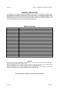
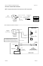
Amplifier Power
Connection Examples
Assumes Power is +VDC
May be powered with
-VDC instead, just change
to -VDC and Amp NEG in
diagrams.
HORN RLY
+VDC
Added
SPDT
Switch
Vehicle
Horn
+VDC
Momentary
SPST
Switch
To Amp POS
Horn
Circuit
Note:
Vehicle horn
will also sound
Vehicle
Horn
S
p
lice
To
Amp POS
To Amp POS
+VDC
Added
Relay
In-line fuseholder
with 15A
Automotive Type Fuse
#18G BRN
#18G BRN
#16G RED to +VDC
#16G BLK to -VDC
Waterproof butt splices
for under hood install
Match lead colors
coming from unit