


Page 4 of 8 HPK-150 Installation and Operating Instructions
02/05/10 CP5061A
MOUNTING
Amplifier
The amplifier is waterproof and may be located under hood in the engine compartment or other
areas. Allow clearance for wiring. Inspect behind mounting area for clearance. Use #8 screws
(supplied loose) for mounting.
Speaker
The speaker is weather resistant and is intended to be mounted on the outside of the vehicle or
under front hood. Mount the speaker facing forward and as far forward on the vehicle as possible
to minimize sound exposure to occupants. Choose a location that minimizes obstructions in front
of the speaker to maximize forward sound. Attach the speaker to a sturdy part of the vehicle to
prevent vibration and possible damage. Attach the speaker angled slightly toward the road so the
front openings will drain off any fluids. Cover openings of speaker while drilling any holes.
DO NOT get metal shavings inside the speaker.
Switch Panel
Mount the switch panel underneath the vehicle dash board using #8 screws (supplied loose).
Locate the panel away from the driver’s or passenger’s legs. Allow clearance for wiring. Inspect
behind mounting area for clearance. Make all electrical connections before final mounting.
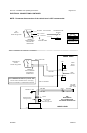
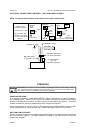
ELECTRICAL CONNECTIONS
Amplifier
Electrical connections to the amplifier are made using butt splices (not supplied). The butt splices
need to be waterproof when unit is mounted under hood or other weather susceptible areas. A
label on the amplifier identifies each lead function. An in-line fuse is provided on the amplifier.
The power supply for the amplifier must be capable of delivering peak currents up to 50 amps for
adequate short circuit protection and reliable operation. Most vehicle horn circuits with relays
provide adequate power on the vehicle horn side of the relay. However do not
provide power to
both the vehicle horn and this amplifier from one horn relay circuit as this will exceed circuit rating.
NOTE: Permanent disconnection of the vehicle horn is NOT recommended.
Switch Panel
Electrical connections to the switch panel are made using 3/16” quick-connect terminals (supplied
loose).
Wire Size and Termination - The diagram shows the minimum wire size used for each connec-
tion, along with recommended lead color. If the wire is longer than 10 ft. use the next larger wire
size. Use only high quality crimp connectors for installation on the vehicle.