


Page 5
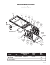
Adjustments and Calibration
$GMXVWPHQW3URFHGXUHV
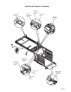
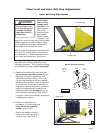
/LIW2XW6ZLWFK The Lift Out Switch stops inward
travel of the carriage/platform during Stow function
(activated by the housing-mounted Lift Out Cam).
Move cam in to increase inward travel. Move cam
out to decrease inward travel. LED D25 will be il-
luminated when the switch is not contacting the cam.
)XOO2XW6ZLWFK7KH)XOO2XW6ZLWFKVWRSVRXW-
ward travel of the carriage/platform during Deploy
(Up/Down) functions (activated by the housing-
PRXQWHG)XOO2XW&DP0RYHFDPLQWRGHFUHDVH
outward travel. Move cam out to increase outward
travel. Carriage rollers must be inside housing a
minimum 1/2". The platform will not raise or lower
until this switch is activated. LED D26 will be illumi-
nated when the switch is contacting the cam.
)ORRU/HYHO6ZLWFK LED D28 will be illuminated
when the switch is contacting the cam. Detailed on
page 6.
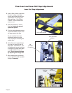
%HORZ6WRZ6ZLWFK The Below Stow Switch
controls the height of the carriage/platform before it
moves inward during the Stow function (activated by
the torque tube-mounted Below Stow Cam). Rotate
the cam in to decrease platform height. Rotate the
cam out to increase platform height. Adjust cam so
OLIWLQJDUPVDUHDOLJQHG9LHZWKHSODWIRUPSRVLWLRQ
in the housing. LED D24 will be illuminated at stow
level and below.
%DUULHU'RZQ6ZLWFK This platform-mounted
switch prohibits the platform from raising unless
the outer barrier is in the full up position. The Up
function is prohibited if the outer barrier detent pin is
not fully engaged also. LED D29 will be illuminated
when the switch is not contacting the outer barrier
detent pin.
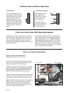
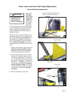
'ULYH&KDLQ$GMXVWPHQW
In event the drive chain sags 1/2" or more, adjust
tension as detailed. Tighten to eliminate visible sag
but do not overtighten.
1. Remove bottom pan.
2. Pull the manual release cable and lock.
3. Remove adjustment bolt (tensioner) access
cover.
4. Loosen inside jam nut. Secure tensioner and
tighten outside jam nut. Tighten to eliminate vis-
ible chain sag but do not overtighten.
5. Lock jam nuts together making sure the ten-
sioner roller is horizontal. Release and push the
manual cable in fully. Ensure platform is locked
by moving the platform in and out until chain
release assembly engages chain.
&DOLEUDWLRQ3URFHGXUHV
3ODWIRUP6HQVH&DOLEUDWLRQ
1. There must be no weight on platform.
2. Press hand held pendant UP switch to raise plat-
form a minimum 3" above stow level.
3. Remove pump cover and press and hold control
board mounted CAL. 50 lb. button. While pressing
the CAL. 50 lb. button, press and hold the hand-
held pendant STOW switch (button). The platform
will lower to stow level (begin stow function), and
then start to raise. Release CAL. 50 lb. button
immediately when platform starts to raise from
stow level.
4. LED D18 will be illuminated when weight on plat-
form prevents stowing.
Ground Sense Calibration
1. Press hand-held pendant DOWN switch to lower
platform fully to ground level.
2. While continuing to press the pendant DOWN
switch, press and then release control board
mounted CALIB. GND SEN/OB button.
3. Release the pendant DOWN switch.
4. LED D23 will be illuminated when platform is at
ground level.
2XWHU%DUULHU2FFXSLHG&DOLEUDWLRQ
1. Press hand-held pendant DOWN switch to lower
platform fully to ground level.
2. Once outer barrier is fully unfolded (ramp posi-
tion), release the pendant DOWN switch.
3. Press and hold the control board mounted CALIB.
GND SEN/OB button. While holding CALIB.
GND SEN/OB button, press hand-held pendant
UP switch to raise the outer barrier. Be sure to
release CALIB. GND SEN/OB button when outer
barrier reaches approximately half full up (verti-
cal) position.
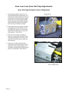
Carriage Ride Height Adjustment
The carriage horizontal arms move (roll) in and out
RIWKHKRXVLQJWUDFNVRQUROOHUEHDULQJV)ROORZ-
ing installation or extensive lift operation, clearance
between horizontal arms and tracks may diminish.
The eccentric shaft mounting plate allows height
adjustment.
Remove eccentric plate mounting screw. Using
screwdriver or small rod, rotate the shaft clockwise
to increase carriage height. Rotate the shaft coun-
terclockwise to decrease carriage height. Reinstall
mounting screw in nearest retainer hole. Adjust left
and right side eccentric shafts (screw positions may
vary from side to side). Adjust height such that hori-
zontal arms do not contact top or bottom of tracks
(align center).