


Braun Corporation FMVSS No. 403 Quick Reference Installation Sheet 31312 Rev. A
Cam
Switch
Screws
Inner
Cam
C
AB
Outer
Cam
Switch
Switch
Arm
Vertical
Arm
Deploy Limit Switch
Screw
Cam
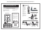
Stepwell Application
Dropped Floor Application
Deploy Limit Switch
Figure Q
Figure R
Figure S
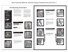
Floor Level Cam Adjustment:
The oor level cam(s) are located on the lower drive
arm shaft, on the rear side of the frame tube (under
the cover). Adjust per application.
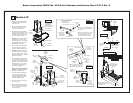
• Stepwell Application (Figure Q)
1. Position platform at oor level.
2. Loosen the two cam screws.
3. Adjust the cam for proper switch activation.
4. Tighten the two cam screws.
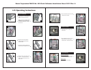
• Dropped Floor Application (Figure R)
• Up-Stop Adjustment (inner cam and switch):
1. Position platform at original oor height
(full up position).
2. Loosen screws A, B and C.
3. Adjust the inner cam for proper switch
activation.
4. Tighten screw B.
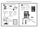
• Floor Level Adjustment (outer cam and
switch):
Activated when the platform switches from the
up/down positions to the stow/deploy positions.
1. Position platform at lowered oor level.
2. Loosen screws A and C.
3. Adjust the outer cam until the oor level
switch activates.
4. Tighten screws A and C.
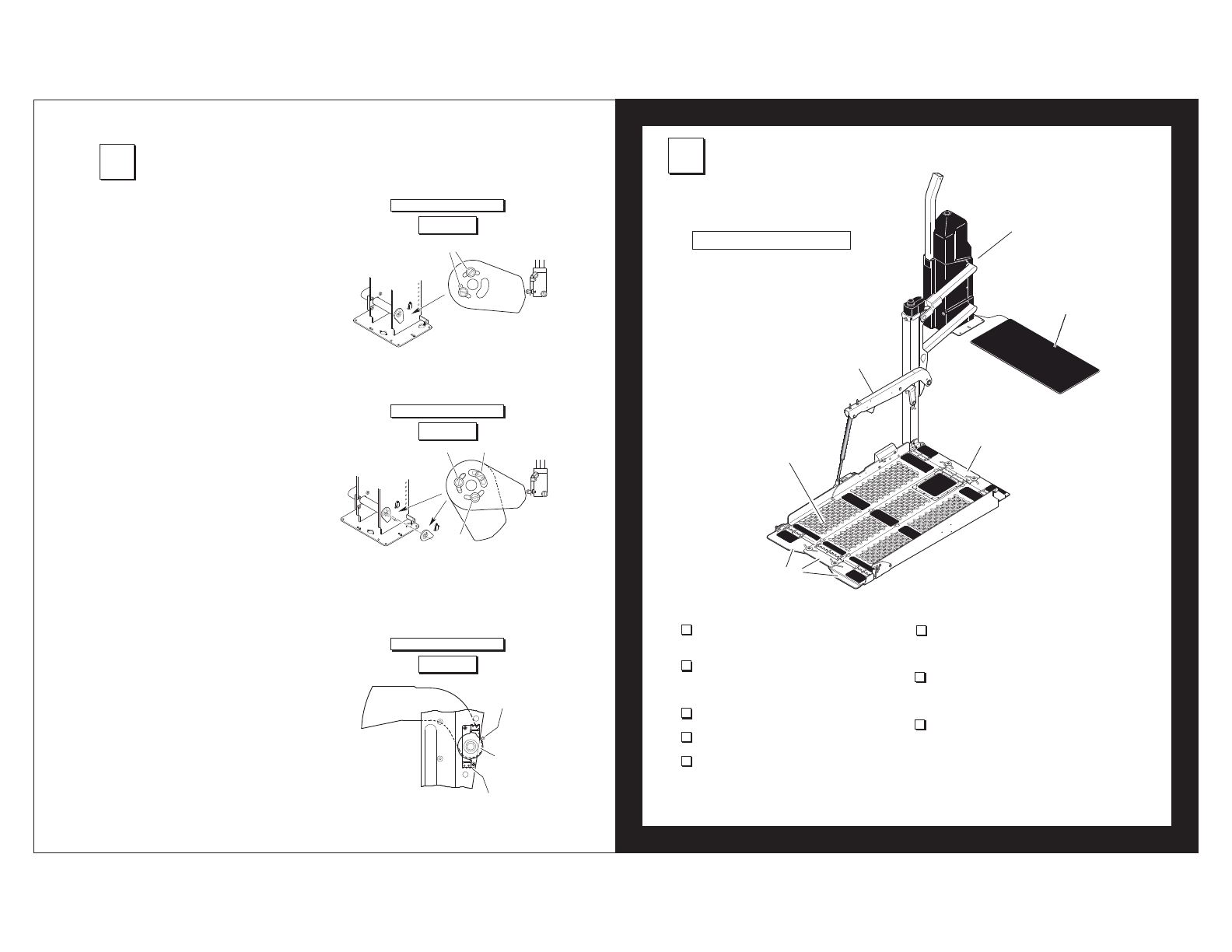
Deploy Limit Switch Adjustment (Figure S)
This switch adjusts the angle of the platform when
positioned at oor level. The platform should be
level with the van oor. The switch is located on the
vertical arm where the switch arm pivots.
1. Position platform at oor level.
2. Loosen the screw that secures the cam to the
vertical arm.
3. Level platform using a level (or as needed).
4. Adjust cam so the deploy limit switch activates.
5. Tighten screw.
6. Verify position and check level.
5
Limit Switch Adjustment
6
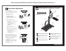
FMVSS 403/404 Certification Checklist
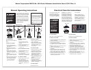
The operations listed below must be func-
tionally veried.
DOT — Private Use Lift
Threshold
Warning Sensor
Audible
Threshold
Warning
Inboard
Locator
Platform
Switch Arm
Outer Barrier
31312 Rev. A
Vehicle movement is prevented unless the lift
door is closed, ensuring the lift is stowed.
Lift operation shall be prevented unless the
vehicle is stopped and vehicle movement is
prevented.
The platform will not fold/stow if occupied.
The inboard locator will not raise if occupied.
The outer barrier will not raise if occupied.
An audible warning will activate if the threshold
area is occupied when the platform is at least
one inch below oor level.
Lowering the platform beyond the inboard loca-
tor locking position is allowed only when the
inboard locator is locked in position.
Lift platform movement shall be interrupted un-
less the outer barrier is deployed.