1800IF - PAGE 14 OF 19
Valvcon Corporation
http://www.valvcon.com
phone: 603-249-9020 fax: 603-249-9140
Cycle Time Adjustments
1) Adjust the ON Indicator for the required ON time of each pulse. The ON adjustment has a nominal range
of 0.05 seconds (when set to 0) to 1 second (when set to 100).
2) Adjust the OFF Indicator for the required OFF time between each pulse. The OFF adjustment has a
nominal range of 1 second (when set to 0) to 1 minute (when set to 100).
3) Run the actuator through a complete open and close cycle. If the ON and OFF readings require
adjustment then repeat steps one and two.
NOTE: Be sure to test the actual time of operation before final usage.
For operation with the heater/thermostat, or retransmit option read the following:
For use with rev. "B" and earlier Cycle Rate Regulator boards, contact Valvcon Express Services at 603-654-
6111 for modification instructions. For use with rev. "C" and above, insure that the trace between the two "X"s on
the back of the 1024 motherboard has been cut. No additional wiring is needed, do not apply option power to
terminals 1 and 2 with the Cycle Rate Regulator option installed.
2.2.3 POSITIONER BOARD OPTION (ORDER CODE "C")
The Valvcon positioner board allows analog control of the valve or damper. That is, the actuator will accept an
analog signal such as 4-20mA and position accordingly: 4mA will be the full clockwise position, 20mA will be full
counterclockwise. Any intermediate signal will be linear with position (i.e., 12mA will be 50% of rotation).
Valvcon manufactures different boards for the different input voltages and control signals. Check the actuator's
baseplate to verify you have the correct board for your application. Available control signals are 4-20mA, 0-
10VDC, 0-1000 Ohm, and 0-135 Ohm. Consult your Valvcon stocking rep for additional signals.
To ensure proper operation of the positioner board, the end-of-travel limit switches should not trip during routine
operation. If you require a feedback signal of valve position, you must have the optional additional limit
switch(es).
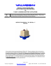
SIGNAL WIRING
Control signal wiring to the actuator should be 20 or 22 AWG shielded wire. The shielding should be grounded to
the actuator housing using one of the motherboard mounting screws. The other end of the shield should be left
unconnected.
Wiring for Units with a Voltage or Current Control Signal
Wiring for Units with a Resistance Control Signal