7
13
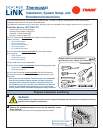
If necessary, cut the internal jumper wire (JP1).
OR
Do NOT cut JP1 jumper
Cut JP1 jumper
If only one wire is connected
to either 24RC or 24RH
as shown
If wires are connected to
both 24RC and 24RH
as shown
Cutting the JP1 jumper
The jumper is located on back of the thermostat face as shown in the illustration to
the right. Cut the jumper using small diagonal cutters being careful not to damage
the board.
15
Turn power to heating and cooling system back on.
The thermostat display should turn on and begin displaying information. If the thermostat display does not come on, go back
throughtheinstallationstepsandlookforproblems.Payspecialattentiontosteps3,3a,and11.
14
Attach the thermostat face to the wall plate.
a. Tuck wiring flat inside the wall plate.
• It is critical that wires are not bunched together and that they are pressed
flat.
b. Carefully align the face plate to the wall plate while aligning pins into wire
terminals.
c. Once thermostat face is properly aligned, apply pressure at top and bottom of
thermostat face until it is secure.
24RC
G
Y1
Y2
RS2
RS2
HC
24C
24RH
W1
W2/O
RS1
RS1
H1
Y1
Y2
Wires
pressed flat
JP1
24C
24RH
W1
W2/O
RS1
RS1
SHLD
HI-NO
24RC
G
Y1
Y2
RS2
RS2
SHLD
HI-C
JP1
JP1