INSTALLATION INSTRUCTIONS
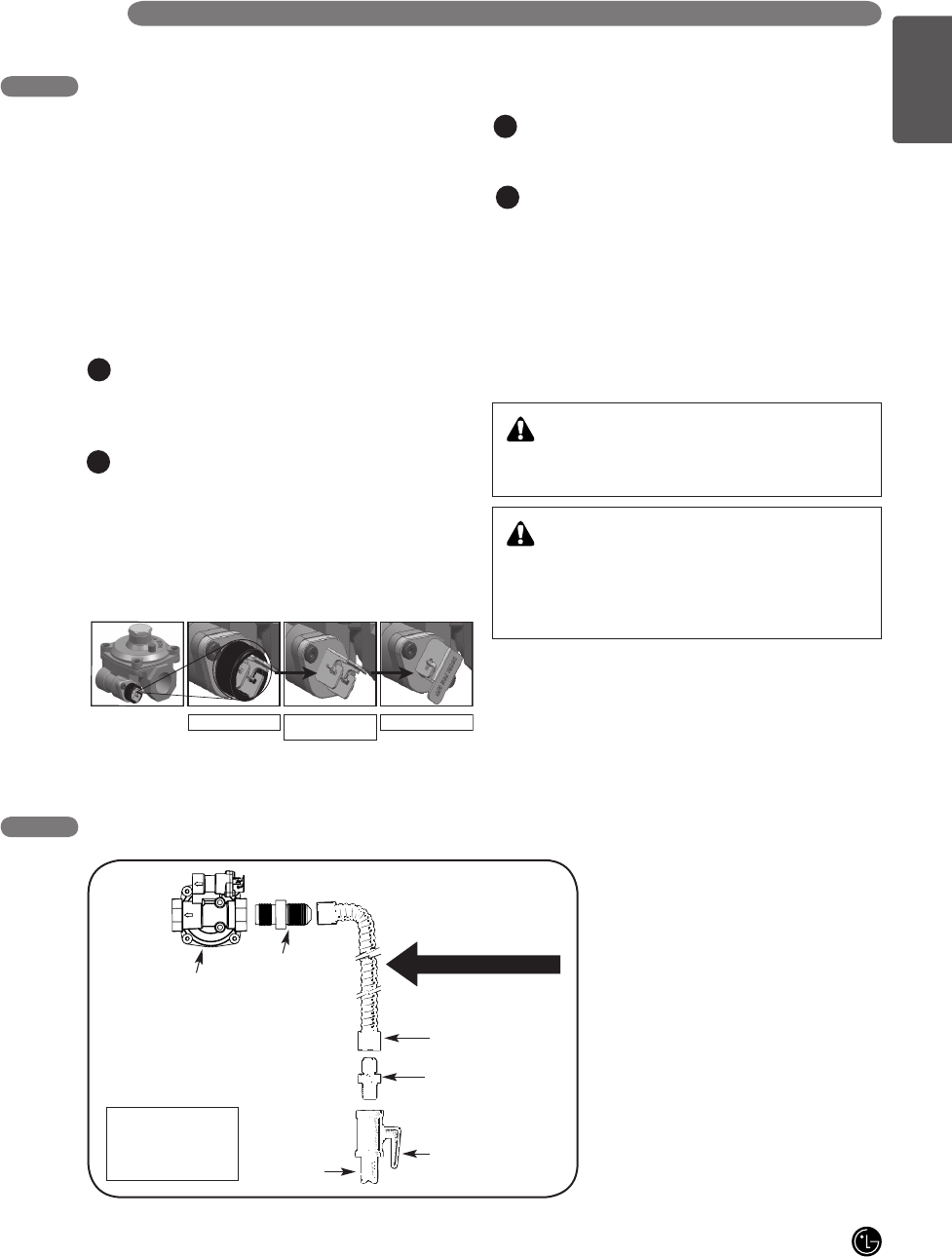
FLEXIBLE CONNECTOR HOOKUP
Pressure regulator
Installer: Inform the
consumer of the
location of the gas
shut-off valve
Adapter
Adapter
Gas shut-off valve
1/2” or 3/4”
Gas pipe
Flex connector
(6 ft. max.)
Gas Flow into Range
Shut off the range gas supply valve before removing
the old range and leave it off until the new hook-up
has been completed.
Because hard piping restricts movement of the range,
the use of a CSA International-certified flexible metal
appliance connector should be used unless local codes
require a hard-piped connection.
NEVER reuse an old connector when installing a new
range.
To protect against gas leaks, use a qualified pipe joint
sealant on all external threads.
Install male 1/2” or 3/4” flare union adapter to the NPT
internal thread of the manual shut-off valve, taking
care to back-up the shut-off valve to keep it from
turning.
Install male 1/2” flare union adapter to the 1/2” NPT
internal thread at inlet of pressure regulator. Use a
backup wrench on the pressure regulator fitting to
prevent damage.
Connect a flexible metal appliance connector to
the adapter on the range. Position range to permit
connection at the shut-off valve.
When all connections have been made, be sure all
range controls are in the off position and turn on the
main gas supply valve. Gas leaks may occur in your
system and result in a dangerous situation. Gas leaks
may not be detected by smell alone.
Check all gas connection joints and fittings for leaks
with a non-corrosive leak detection fluid, then wipe off.
Gas suppliers recommend you purchase and install
an UL approved gas detector. Install and use in
accordance with Installation instructions.
2. CONNECT THE RANGE TO GAS
A
C
B
D
DO NOT USE A FLAME TO CHECK FOR GAS
LEAKS.
WARNING!
Isolate the range from the gas supply system by
closing its individual shut-off valve during any pressure
testing of the gas supply system at test pressures
equal to or less than 1/2” psig(3.5kPa).
WARNING!
In a emergency situation or if you want to shut off
the gas suppluy, remove the packing rubber from the
regulator in the backside, and then close the regulator's
valve by positioning the lever as shown in the figure.
Lever’s open position Lever’s open position
(without rubber O-ring)
Lever’s close position
