69-1037
3
T8411R ELECTRONIC HEAT PUMP THERMOSTAT
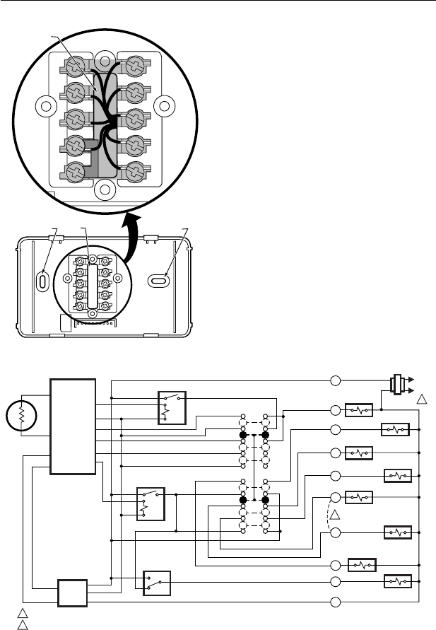
Fig. 4. Restrict wiring to shaded area.
NOTE: Restrict all wiring to the shaded area between the
terminals. See Fig. 4.
Refer to Fig. 5 for typical wiring hookup. A letter code is
located near each terminal for identification.
1. Loosen the terminal screws on the wallplate and
connect the system wires. See Fig. 5.
2. Securely tighten each terminal screw.
3. Push the excess wire back into the hole.
4. Plug the hole with nonflammable insulation to
prevent drafts from affecting the thermostat.
Mounting Thermostat To Wallplate
1. Engage the tabs at the top of the thermostat and
wallplate.
2. Swing down the thermostat and press the lower
edge of the thermostat onto the wallplate to latch.
See Fig. 6.
Fig. 5. T8411R two-stage heat and one-stage cool wiring diagram with manual changeover.
KEEP WIRING IN
SHADED AREA
MOUNTING
SCREW HOLE
MOUNTING
SCREW HOLE
WIRING ENTRANCE
HOLE
M11331
G
C
R
Y
W1
L
W2
E
B
O
L1
(HOT)
L2
1
1
2
2
POWER SUPPLY. PROVIDE DISCONNECT MEANS AND OVERLOAD PROTECTION AS REQUIRED.
REMOVE JUMPER, WHEN SUPPLIED, FOR SYSTEMS WITH SEPERATE HEATING COMPRESSOR CONTACTOR (W1 SEPARATE FROM Y).
SYSTEM
SWITCH
HEAT
OFF
COOL
R
W2
L
B
O
Y
EM. HT.
W1
E
AUXILARY
HEAT RELAY
CHANGEOVER
VALVE HEAT
CHANGEOVER
VALVE COOL
COMPRESSOR
CONTACTOR
COMPRESSOR
CONTACTOR
HEAT
FAN RELAY
RELAY
EMERGENCY
HEAT RELAY
G
C
THERMOSTAT
LOGIC
THERMISTOR
SENSOR
POWER
SUPPLY
ON
AUTO
STAGE 2 RELAY
STAGE 1 RELAY
FAN SWITCH
M11333


