Instruction Manual
IB-106-340C Rev. 4.1
July 2004
Rosemount Analytical Inc. A Division of Emerson Process Management Startup and Operation with LOI 6-7
Hazardous Area Oxymitter 4000
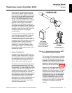
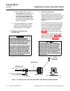
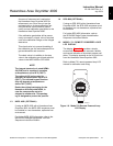
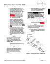
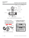
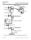
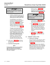
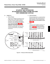
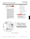
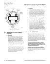
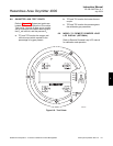
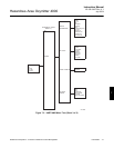
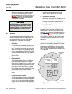
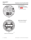
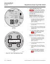
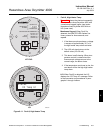
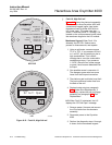
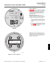
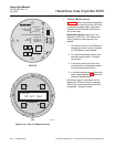
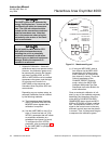
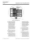
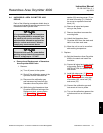
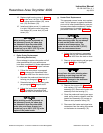
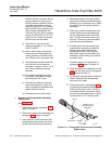
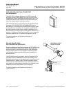
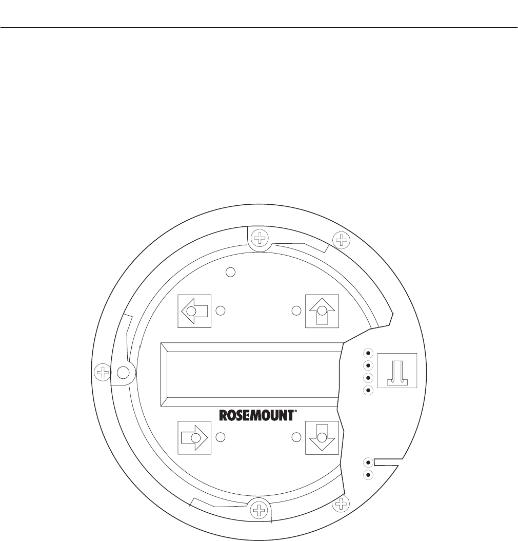
6-8 OXYMITTER 4000 TEST POINTS
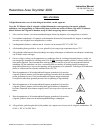
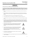
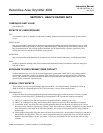
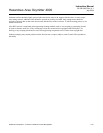
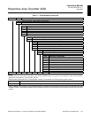
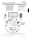
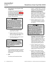
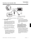
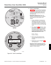
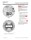
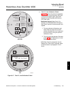
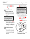
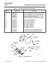
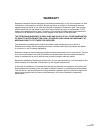
Refer to Figure 6-6. System test points are
located on the board below the LOI module.
Test points 1 through 6 allow you to monitor
with a multimeter: the heater thermocouple,
the O
2
cell millivolt, and the process O
2
.
a. TP1 and TP2 monitor the oxygen cell
millivolt output which equates to the
percentage of oxygen present.
b. TP3 and TP4 monitor the heater thermo-
couple.
c. TP5 and TP6 monitor the process gas or
the calibration gas parameter.
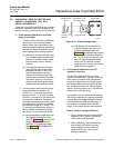
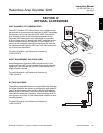
6-9 MODEL 751 REMOTE POWERED LOOP
LCD DISPLAY (OPTIONAL)
Refer to Remote Powered Loop LCD manual
for calibration and operation.
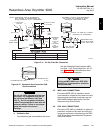
TP1
J1
TP2
TP3
RED
YEL
GRN
ORG
TP4
TP5
TP6
37260037
Figure 6-6. Test Points