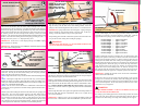
SCREW EYE AT 48 TO 50
(1220 to 1270 mm) FROM FLOOR
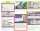
PULL ROPE
TIE PULL ROPE TO
BOTTOM BRACKET
19
Twist the No. 6 screw eye into the wood jamb approximately 48 to 50 (1220 to
1270 mm) from the floor. Tie the pull rope to the screw eye and to the bottom
bracket as shown.
WARNING!
DO NOT INSTALL PULL ROPES ON DOORS WITH ELECTRIC OP-
ERATORS. CHILDREN MAY BECOME ENTANGLED IN THE ROPE
CAUSING INJURY OR DEATH.
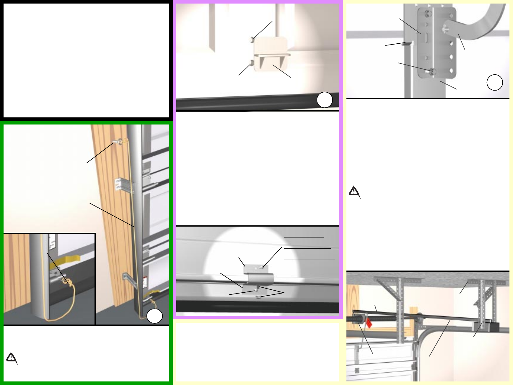
ATTACH OPERATOR
RAIL SECURELY TO
SPRING PAD
ATTACH OPERATOR
TO CEILING USING
PERFORATED ANGLE
IMPORTANT! ANGLE MUST
BE ATTACHED TO FRAM-
ING MEMBER(S)
INSTALL TROLLEY RAIL 1 TO 1-1/2
(25 - 38 mm) ABOVE DOOR WHEN
FULLY OPEN (RAIL WILL SLOPE
DOWN)
INSTALL FRONT OF
TROLLEY RAIL 1
TO 1-1/2 (25 - 38
mm) ABOVE HIGH-
ARC OF DOOR
TYPICAL OPERATOR
BRACKET (SUPPLIED
WITH OPERATOR)
SCREWS (SUPPLIED
WITH OPERATOR)
TYPICAL OPERATOR
ARM (SUPPLIED
WITH OPERATOR)
SEE OPERATOR INSTRUCTIONS
FOR DETAILS ON INSTALLATION
OPERATOR
MUNTIN
21
INSTALLATION TIPS:
1. Follow the installation instructions supplied with your operator.
2. Reinforce top section per manufacturers recommendation prior to attaching
operator.
3. Install trolley rail 1 to 1-1/2 (25 - 38 mm) above high arc of top section of
the door.
4. Mount operator to ceiling so that 1 to 1-1/2 (25 - 38 mm) clearance is
maintained between trolley rail and top section when door is fully open (trolley
rail will slope down towards rear).
5. The operator bracket must be mounted to the operator muntin on the top
section so it bridges the transition point in section thickness.
WARNING!
OPERATOR MUST BE TESTED AT TIME OF INSTALLATION AND
MONTHLY THEREAFTER TO ENSURE THAT DOOR REVERSES ON
CONTACT WITH 2 X 4 BOARD LAID FLAT UNDER THE DOOR. FAIL-
URE TO ADJUST OPERATOR, IF NECESSARY, CAN RESULT IN SE-
VERE INJURY OR DEATH. IF YOUR OPERATOR IS EQUIPPED WITH
PHOTOELECTRIC SYSTEM, THEN THIS MUST BE TESTED AT THE
SAME TIME TO ENSURE THAT DOOR DOES NOT CLOSE AND A
CLOSING DOOR OPENS IF SYSTEM IS OBSTRUCTED. FAILURE
TO MAKE ADJUSTMENTS, IF NECESSARY, CAN RESULT IN SEVERE
INJURY OR DEATH.
BRIDGE POINT
If the door still does not operate easily, lower the door into the closed position,
UNWIND THE SPRING(S) FULLY (Reference the insert sheet Removing the
Old Door/Preparing the Opening section on Torsion Spring Removal), and re-
check the following the items:
1.) Check the door for level.
2.) Check the torsion tube for level.
3.) Check the track spacing.
4.) Check the counterbalance cables for equal tension.
5.) Check for track for potential obstruction of the rollers.
6.) Clamp locking pliers onto track and rewind spring(s).
IMPORTANT! If door still does not operate properly, then contact a qualified
door agency.
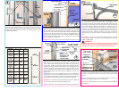
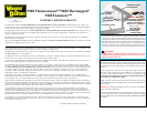
OUTSIDE
STEP PLATE
BOTTOM SECTION
(OUTSIDE)
1st HOLE AT 1
(25 mm) FROM
BOTTOM OF
SECTION
2nd HOLE AT 2-3/16
(56 mm) FROM 1st HOLE
BOTTOM SECTION
(INSIDE)
20
INSIDE STEP
PLATE BASE
To install the step plate raise the door to a comfortable working height and
secure with locking pliers to the track. Locate the step plate in the center of
any stile on a raised panel door. Make one mark 1 (25 mm) up from the
bottom edge and another mark 2- 3/16 (56 mm) up from the first mark. Drill
a 7/16 (11 mm) hole through the section at each mark and insert the step
plate. Loosely fasten step plate slide to base with (1) 1/4-20 x 1/2 carriage
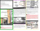
bolt and nut. Align inside step plate holes and fasten from inside using the #8
screws provided. Install one #8 x 3/4 screw in the bottom step plate hole. In
the top hole use the #8 x 3/4 screw when attaching step plates to 9200
Foamcore, use the #8 x 1 screw when attaching step plates to 9600
Thermogard
®
and use the #8 x 1-1/2 screw when attaching step plates to 9900
Thermowayne. Tighten 1/4-20 carriage bolt and nut.
NOTE: Step plates are optional on 9900 Thermowayne, 9600 Thermogard
®
,
and 9200 Foamcore door models.
TYPICAL OPERATOR INSTALLATION
If you are installing an electric operator on your door, the following informa-
tion is provided to ensure proper function of your door/operator installation.
Figure 21 shows a typical means of connecting the operator arm to the opera-
tor stile located in the center of the top section.
INSIDE STEP
PLATE SLIDE
1/4-20 X 9/16
CARRIAGE BOLT
AND WHIZ NUT
#8 x 3/4 SCREW
#8 x 3/4 SCREW
9200 FOAMCORE
#8 x 1 SCREW
9600 THERMOGARD
#8 x 1-1/2 SCREW
9900 THERMOWAYNE


