THGIEHROOD1-LT2-LT3-LT
"0'6
KCART"46
)mm6261(
MOTTOBMOTTOBA/N
"5'6
KCART"96
)mm3571(
ELDDIMMOTTOBA/N
"6'6
KCART"07
)mm8771(
ELDDIMMOTTOBA/N
"8'6
KCART"27
)mm9281(
MOTTOBMOTTOBA/N
"0'7
KCART"67
)mm0391(
ELDDIMMOTTOBA/N
"3'7
KCART"97
)mm7002(
MOTTOBMOTTOBMOTTOB
"6'7
KCART"28
)mm3802(
ELDDIMELDDIMELDDIM
"9'7
KCART"58
)mm9512(
ELDDIMELDDIMELDDIM
"0'8
)SNOITCES4(
)SNOITCES5(
KCART"88
)mm5322(
ELDDIM
POT
ELDDIM
POT
ELDDIM
ELDDIM
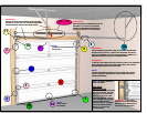
FLAGANGLE
HORIZONTAL
ANGLE
ALIGN
EDGE OF
SECTIONS
(2) 1/4-20 x 5/8 SELF
TAPPING SCREWS
END HINGE #1
ON BOTTOM
SECTION
BOTTOM JAMB
BRACKET
VERTICAL
TRACK
NOTE:
IDENTIFY LOCK
SECTION BY THE
#2 STAMP ON
THE END HINGE
5/16 x 1-5/8
LAG SCREW
CENTER
HINGE
(3) 1/4-20 x 5/8 SELF
TAPPING SCREWS
TL-3
HOLES
TL-1
HOLES
TL-2
HOLES
BOTTOM
SECTION
VERTICAL
TRACK
FLAGANGLE
5/16 x 1-5/8
LAG SCREW
CENTER JAMB
BRACKET
COUNTERBALANCE
CABLE
CABLE DRUM
ROUND
NOTCH
NOTE: Jamb brackets are stamped for identification.
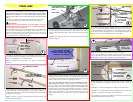
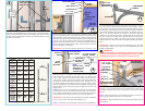
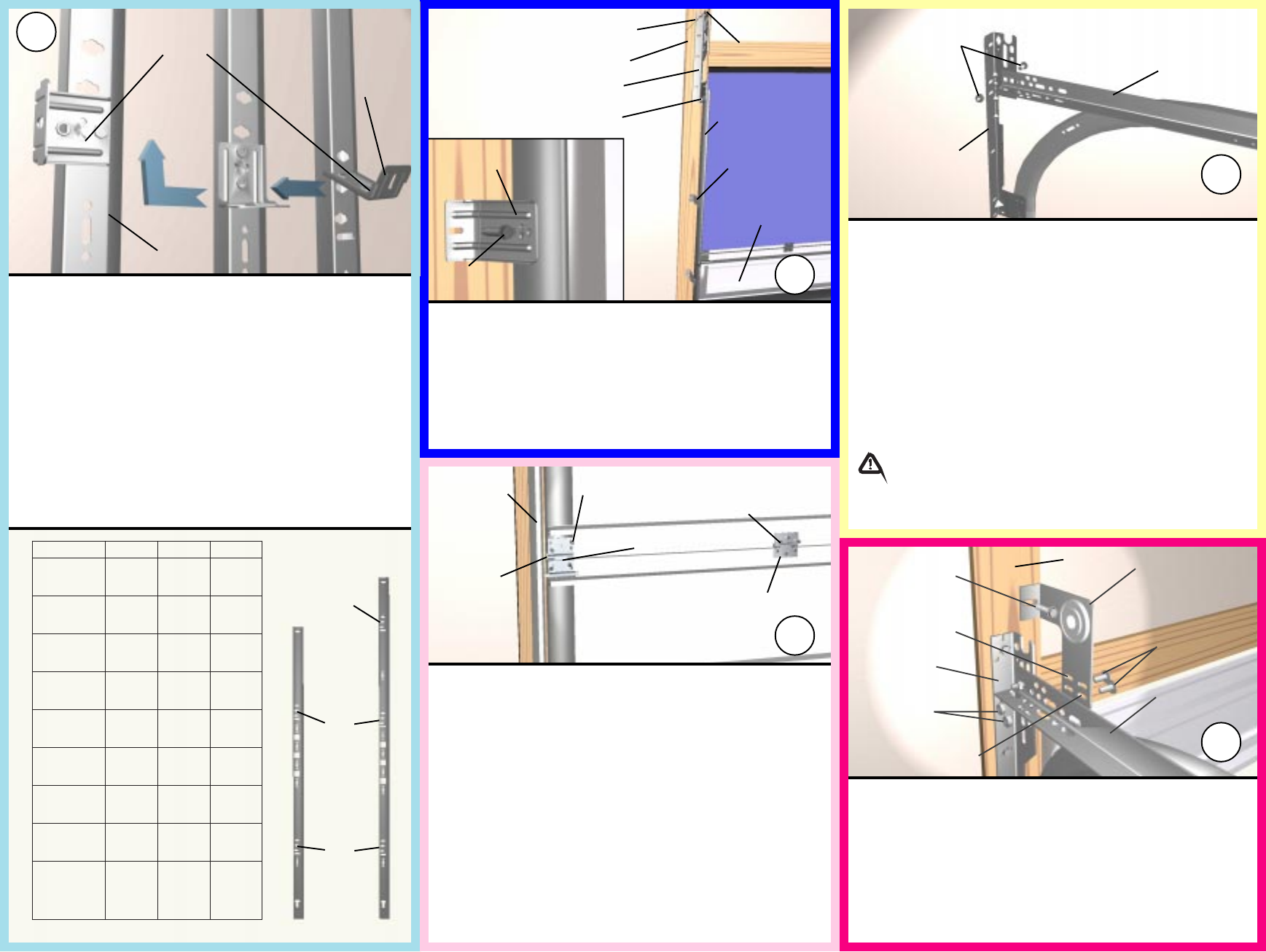
Position the first vertical track over the rollers of the bottom section. Make
sure the counterbalance cable is located between the rollers and the door jamb.
Align the marks on the vertical track from step 3 with the vertical track line
stamp on the endcap and loosely fasten bottom jamb bracket and flagangle with
(1) 5/16 x 1-5/8 lag screw each, but do not secure the center jamb bracket yet.
Install the other vertical track the same way. Run the counterbalance cables up
between vertical track and edge of door section. Hang the cables over the tops
of the the flagangles in round notch.
IMPORTANT! The tops of the vertical tracks must be level from side to side.
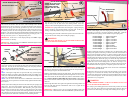
Make sure top leaves of all hinges on the bottom section are folded down.
Insert rollers into the end hinges of the second section, also called the lock
section. With assistance lift section and place rollers over the tops of the
vertical tracks. Install by guiding rollers into the vertical track on both sides
and gently lowering this section onto the bottom section. Keeping the ends of
the sections aligned, install remaining section(s), except top section, in same
manner. Fasten all hinges to connect the sections by flipping up the hinge leaf,
holding it firmly against section and driving in the supplied 1/4-20 x 5/8 self
tapping screws.
NOTE: Two (2) 1/4-20 x 5/8 self tapping screws are used for each end hinge
leaf, while three (3) screws are used for each center hinge. The screw place-
ment is staggered in the end hinges, with the screw nearest the edge of the door
going into the lower hole and the inside screw going into the upper hole.
IMPORTANT! Once fastener is snug against hinge leaf, tighten an additional
1/4 to 1/2 turn to achieve maximum design holding power.
NOTE: To install lock, see lock instructions included in the lock assembly bag.
To install horizontal track, place the curved end over the top roller. Align the
key slot in the track with the quick install tabs on the flagangle. With a
pivoting motion, push the curved portion of the horizontal track downward to
lock into place, while raising the rear of the horizontal to align the horizontal
angle with the flagangle. Bolt the horizontal angle to the flagangle using (1)
3/8-16 x 3/4 truss head bolt and nut. Repeat for other side. With track
installed you can adjust the top brackets. Vertically align the top section with
the lower sections. Once aligned, move adjustable slide out to force top roller
against horizontal track. Tighten 1/4-20 nuts to secure slide to top bracket.
Repeat for other side. Remove nail that was temporarily holding top section in
place.
IMPORTANT! Failure to remove nail before attempting to raise door could
cause permanent damage to top section. DO NOT ATTEIMPT TO RAISE
DOOR AT THIS POINT.
WARNING!
DO NOT RAISE DOOR UNTIL HORIZONTAL TRACKS ARE SECURED
AT REAR AS OUTLINED IN STEP #18, OR DOOR COULD FALL FROM
OVERHEAD POSITION CAUSING SEVERE INJURY OR DEATH.
6
7
11
3/8-16 x 3/4
TRUSS HEAD
BOLT & NUT
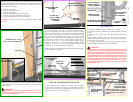
Attach the left hand end bearing bracket to the horizontal angle with
(2) 3/8-16 x 3/4 truss head bolts and nuts. Once the bracket is secured, fasten
the bracket to the jamb with (1) 5/16 x 1-5/8 lag screw. Repeat for the right
hand side.
NOTE: End bearing brackets are to be attached using the lower slots on 12
radius track and using the upper slots on 15 radius track.
IMPORTANT! Right and left hand are always determined from inside the build-
ing looking out.
LEFT HAND END
BEARING BRACKET
UPPER SLOTS
USED ON 15
RADIUS TRACK
(2) 3/8 - 16
HEX NUTS
FLAGANGLE
LOWER SLOTS USED
ON 12 RAD. TRACK
5/16 X 1-5/8
LAG SCREW
(2) 3/8-16 x 3/4
TRUSS HEAD
BOLT
HORIZONTAL
ANGLE
12
JAMB
JAMB
BRACKET
ALIGN IN PROPER
HOLE AND TWIST TO
BACK OF TRACK
VERTICAL TRACK
3
Measure the length of the vertical tracks. Using the table, determine the
placement of the jamb brackets for your door height. Align the Twistlock
wings on each jamb bracket with the correct butterfly hole in the track and turn
the jamb bracket perpendicular to the track so the mounting flange is toward
the back leg of the track.


