FLAGANGLE
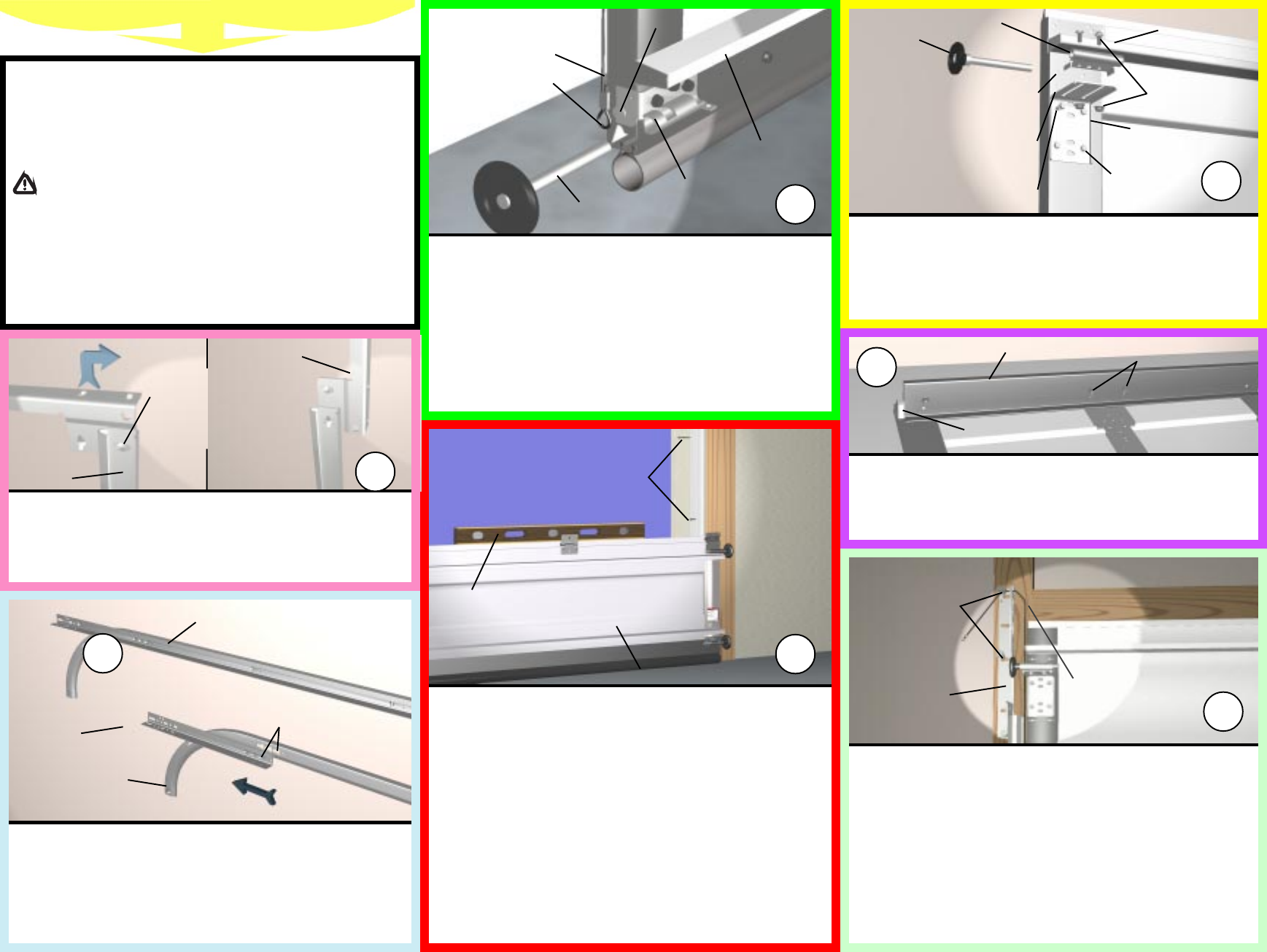
(2) 5/16 x 1-5/8
LAG SCREW
TOP SECTION
NOTE: CABLE SHOULD
BE BETWEEN TRACK
AND DOOR AND
BEHIND ROLLERS
10
8
TOP BRACKET
(4) 1/4-20 x 5/8
SELF TAPPING
SCREWS
1
ST
SET OF HOLES ON
9900 THERMOWAYNE
2
ND
SET OF HOLES ON
9600 THERMOGARD
®
3
RD
SET OF HOLES ON
9200 FOAMCORE
3 U-BAR
TOP SECTION
TOP RIB
FOAMCORE II
(MODEL 9200)
TOP SECTION
1/4-20 x 5/8 SELF
DRILLING SCREW
(2) 1/4-20
CARRIAGE BOLTS
AND NUTS
TOP BRACKET
SLIDE
ROLLER
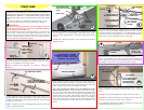
To install the L-shaped top brackets, align the top holes in the top bracket with
the first set of holes in the endcap for 9900 Thermowayne doors, second set
for 9600 Thermogard
®
doors and third set on all 9200 Foamcore doors.
Fasten using (4) 1/4-20 x 5/8 tapping screws. Secure the top bracket slide to the
bracket using (2) 1/4-20 carriage bolts and nuts. Insert rollers.
9200 Foamcore doors over 13 wide require a 3 U-Bar. Center the U-Bar over
the top rib on the top section and secure it to the section using (6)
1/4-20 x 5/8 self drilling screws. Place top section in the door opening and
secure it temporarily by driving a nail into the header near the center of the door
and bending it over the section. Now flip, hold and fasten the hinges.
9
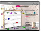
TOP SECTION
RIB
LEFT HAND
BOTTOM
BRACKET
BOTTOM
SECTION
ROLLER
COUNTERBALANCE
CABLE FOR LEFT HAND
DRUM
CABLE LOOP
BOTTOM ASTRAGAL
LEVEL
VINYL WEATHER STRIPPING
TEMPORARILY NAILED TO JAMBS
(REFER TO INSERT SHEET ON
PREPARING THE OPENING.)
MILFORD
PIN
4
FLAGANGLE
ALIGN TAB INTO
TOP HOLE IN
TRACK AND
TWIST UP UNTIL
PARALLEL WITH
TRACK
ALIGN TABS INTO SLOTS,
PUSH TOGETHER AND TAP
FORWARD WITH HAMMER
START HERE
5
1
IMPORTANT! READ IMPORTANT SAFETY NOTICES AND REFER TO
INSERT SHEET INSTRUCTIONS TITLED REMOVING THE OLD DOOR/
PREPARING THE OPENING. IF THE INSERT SHEET INSTRUCTIONS
ARE NOT INCLUDED, CONTACT WAYNE-DALTON CORP. FOR A FREE
COPY.
If removing an existing door, carefully follow the directions given on the
insert sheet instruction in the portion titled Removing the Old Door.
WARNING!
REMOVAL OF AN EXISTING DOOR CAN BE DANGEROUS. FOLLOW
INSERT SHEET INSTRUCTIONS CAREFULLY, OTHERWISE SERIOUS
INJURY OR DEATH COULD RESULT.
Begin the installation of the door by checking the opening. It must be the same
size as the door. Vertical jambs must be plumb and the header level. Side
clearance, from edge of door to wall, must be minimum of 3-1/2 (89 mm) on
each side. For proper opening preparation refer to the portion of the insert
sheet instructions titled Preparing the Opening.
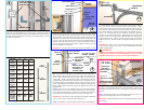
Assemble the Wayne-Dalton Twistlock, Slidelock track system. First,
put the Twistlock tabs on the flagangle into the Twistlock holes on the vertical
track. Give the flagangle 1/4 turn to lock in place.
NOTE: Twistlock track components - U.S. patent no. 5,408,724 and
5,568,672.
Align the Slidelock tabs on the applicable horizontal angle with key slots in
the horizontal track. Push the parts together. Using a hammer, tap the hori-
zontal angle towards the curved end of the track until the hole in track and angle
are aligned. Set tracks aside.
NOTE: For larger size doors, a full length horizontal angle is already spot
welded to the horizontal track.
Uncoil the counterbalance cables and slip the loops at the ends of the cables
over the milford pins on the bottom brackets of the bottom section. Place a
roller in each of the bottom brackets, as well as the end hinges at the top of the
section.
IMPORTANT! Right and left hand is always determined from inside the
building looking out.
Before installing the bottom section, measure and cut vinyl jamb weather-
stripping for entire garage door opening. Temporarily nail the weather-strip-
ping to the door jambs and header. This will help hold the bottom door section
in place. Refer to the insert sheet on preparing the opening.
Now comes the single most important step in installing the Wayne-
Dalton garage door system. Center the bottom section in the door open-
ing. Level it using wooden shims under the bottom astragal as needed. Once
the bottom section is level, all the other components will automatically align.
Hold the section in the opening while attaching vertical tracks. Align the
bottom of the vertical tracks with the bottom of the section. If you leveled the
bottom section with shims on one side, then the vertical track on that side
must be raised off the floor an amount thats equal to the thickness of the
shim(s).
80 HORIZONTAL ANGLE
Position the flagangle 1-11/16 (43 mm) from the edge of the door. Tighten the
first lag screw then secure flagangle to the jamb with (2) 5/16 x 1-5/8 lag
screws.
IMPORTANT! Ensure that flagangles are parallel with the door sections.
IMPORTANT! The dimension between the flagangles must be exactly door-
width plus 3-3/8 (86 mm) for smooth, safe door operation.
Now complete the vertical track installation on both sides by securing center
jamb bracket and tightening other lag screws.
22-1/2
HORIZONTAL
ANGLE
HORIZONTAL
TRACK
VERTICAL
TRACK
2


