


VXI Technology, Inc.
22 CT-100B Installation
RACK MOUNT KIT INSTALLATION
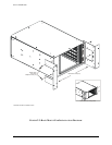
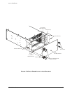
The rack mount kit (Option 59) provides the basic hardware necessary to rack mount the
CT-100B chassis. With the chassis being only 15” wide, standard rack support rails cannot
provide mechanical support to the chassis. If the equipment mounted below the CT-100B cannot
provide mechanical support to the chassis, either 20” or 24” rack slides will be required to support
the chassis when installed into the rack. The rack mounting ears are designed to allow the chassis
to be flush mounted in the rack or recessed 4”.
REQUIRED TOOLS
1. #2 Phillips Screwdriver
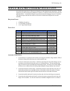
PARTS LIST
QTY ITEM VTI P/N
4 Screw, 6-32 x 1/2", Phillips/Sems 37-0028-050
1 Bracket, Rack Flange w/ hinge mounting holes 41-0135-000
1 Bracket, Rack Flange 41-0135-001
ASSEMBLY PROCEDURE
1. Remove the four (4) black plastic feet from the bottom of the chassis.
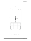
2. Lay the chassis on a protected work surface on its long side with the voltage monitor LEDs of
the chassis facing front with the power switch toward the top.
3. Locate and remove four black plastic feet on the side of the chassis and four black plastic feet
on the bottom of the chassis. Retain the feet if restoring the chassis to its original portable use
is anticipated.
4. Find two threaded holes on each side of the chassis (the plastic feet were attached to two of
these holes) towards the front of the unit.
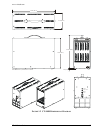
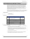
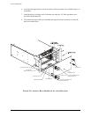
5. Line up the rack mount ears with the threaded holes selecting the flush or recessed position as
desired. Refer to the rack mount ear installation diagram for visual assistance.
6. Secure the rack ears using the supplied #8-32 hardware.
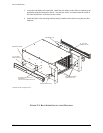
Before installing the chassis into an EIA switch rack, the chassis handle should be removed. This
can be done by doing the following:
1. Remove the four screws located near the handle.
2. Remove the two black decorative covers at each end of the carrying handle using the flat
blade screwdriver. Place a piece of paper under the screwdriver blade to prevent scratching
the chassis cover.
3. Remove the four Phillips screws holding the handle in place and then remove the handle
itself. Retain the carrying handle components if there may be some need to restore the
chassis to its original portable use in the future.