www.vxitech.com
CT-100B Installation 19
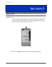
SECTION 2
INSTALLATION
INTRODUCTION
When the CT-100B is unpacked from its shipping carton, the contents should include the
following items:
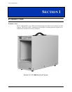
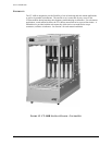
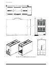
(1) CT-100B Six-Slot Chassis
(1) CT-100B Module User’s Manual (this manual)
(2) Replacement fuses, one 10 A slow blow, one 5 A slow blow
(1) Power cord
All components should be immediately inspected for damage upon receipt of the unit.
LINE VOLTAGE SELECTION
The CT-100B provides auto-ranging power supplies, which automatically sense the line power
value and set themselves accordingly. Ensure that the fuse is correctly rated for the selected line
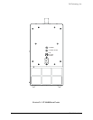
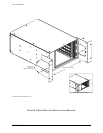
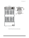
voltage (the CT-100B is factory configured with a 10 A/115 V fuse). The fuse is located in fuse-
holder F1 on the rear panel of the chassis. The correct fuse ratings are:
115 V operation 10 A slow blow
220 V operation 5 A slow blow
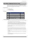
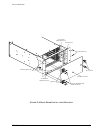
See Figure 2-1 for the location of the line fuse.
CAUTION
Do not attempt to change the fuse with the line cord connected. Ensure that power is off
and that the unit is unplugged before changing the fuse.
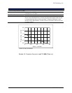
BACKPLANE
The CT-100B has a jumper-less auto-configurable backplane using active-automatic daisy
chaining for the VME Interrupt acknowledge and bus grant daisy chain signal lines. This
eliminates the need to manually configure the backplane.