9
Needle valve,
set flow to 800
cc/min (+/- 10%)
Chassis
Sample
Zero
Exhaust
Vent Span
Pressure Span
To Purge
Sample
gas
From Purge
Flowmeter
Pressure
regulator, set
output to 5-10
psig
10-30 psig
CO2 free gas
Span gas
CO2 free
gas
Pressure
Regulator (5-10
psig output)
Needle valve,
set flow to 800
cc/min (+/-
10%)
Pressure
Regular (5-10
psig output)
Needle valve,
set flow to 800
cc/min (+/-
10%)
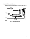
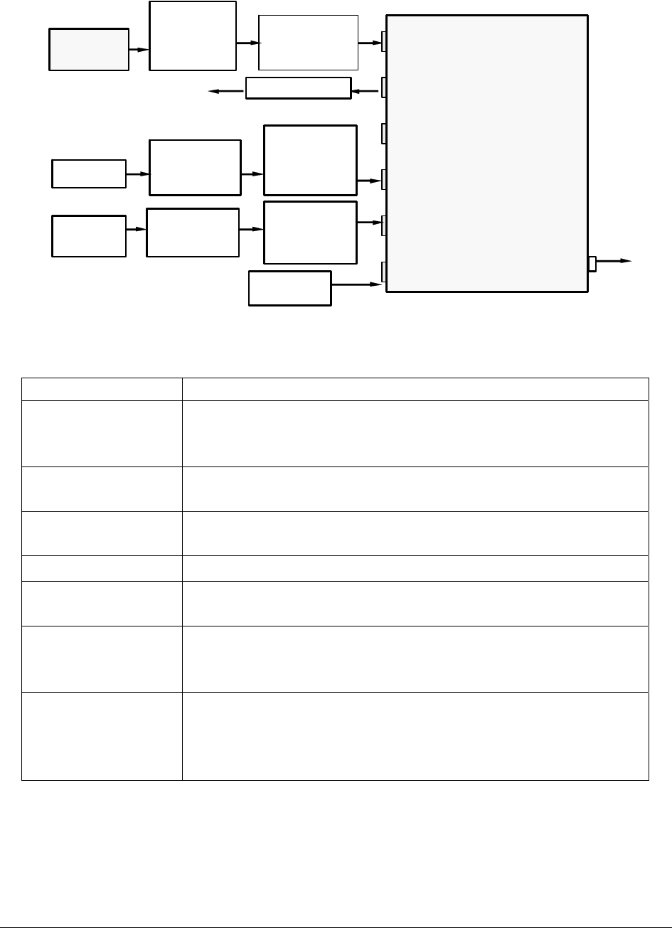
Figure 4-3. Pneumatic Connections–Configuration with Zero/Span Valve Option
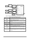
Table 4-1. Model T360U Pneumatic Connections
Rear Panel Label Function
SAMPLE
Connect a gas line from the source of sample gas here.
Calibration gasses are also inlet here on units without
zero/span valve option installed.
EXHAUST
Connect an exhaust gas line of not more than 10 meters
long here.
PRESSURE SPAN
On units with zero/span valve option installed, connect a
gas line to the source of calibrated span gas here.
VENT SPAN Not used
ZERO
On units with zero/span valve option installed, attach a
gas line to the source of zero air here.
TO PURGE
This inlet supplies purge air to the GFC wheel housing
Connect a source of dried air that has been scrubbed of
CO
2
.
FROM PURGE
This exhausts purge air from the GFC wheel housing.
Connect an exhaust gas line of not more than 10 meters
long here.


