Trace Oxygen Analyzer Installation
Teledyne Analytical Instruments 19
• Vent connection
• Coalescing filter drain
Note: Zero gas is not required however, see Section 5.2.1.
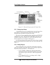
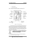
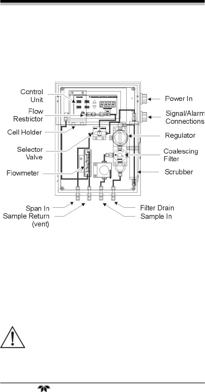
Figure 3-3: Gas Connections
To connect the gas lines, remove the fitting and ferrule and cone at
the bottom panel. Insert the tubing into the fitting then place the ferrule
and cone over the tubing. Mate the assembly back to the connector on
the panel and tighten finger tight. Use a wrench to tighten an additional
1 ¼ turn beyond finger tight. You may have to hold the stationary fitting
with another wrench to keep the entire fitting from turning. Figure 3-3
shows the gas connection panel.
CAUTION: TIE IN ONE LINE AT A TIME. MAKE SURE THAT THE
CORRECT GAS LINE IS MATED TO THE PROPER
FITTING ON THE INSTRUMENT.
For maximum performance, the system should be installed in a
manner to minimize the sample line length.


