Trace Oxygen Analyzer Installation
Teledyne Analytical Instruments 15
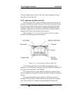
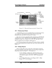
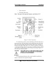
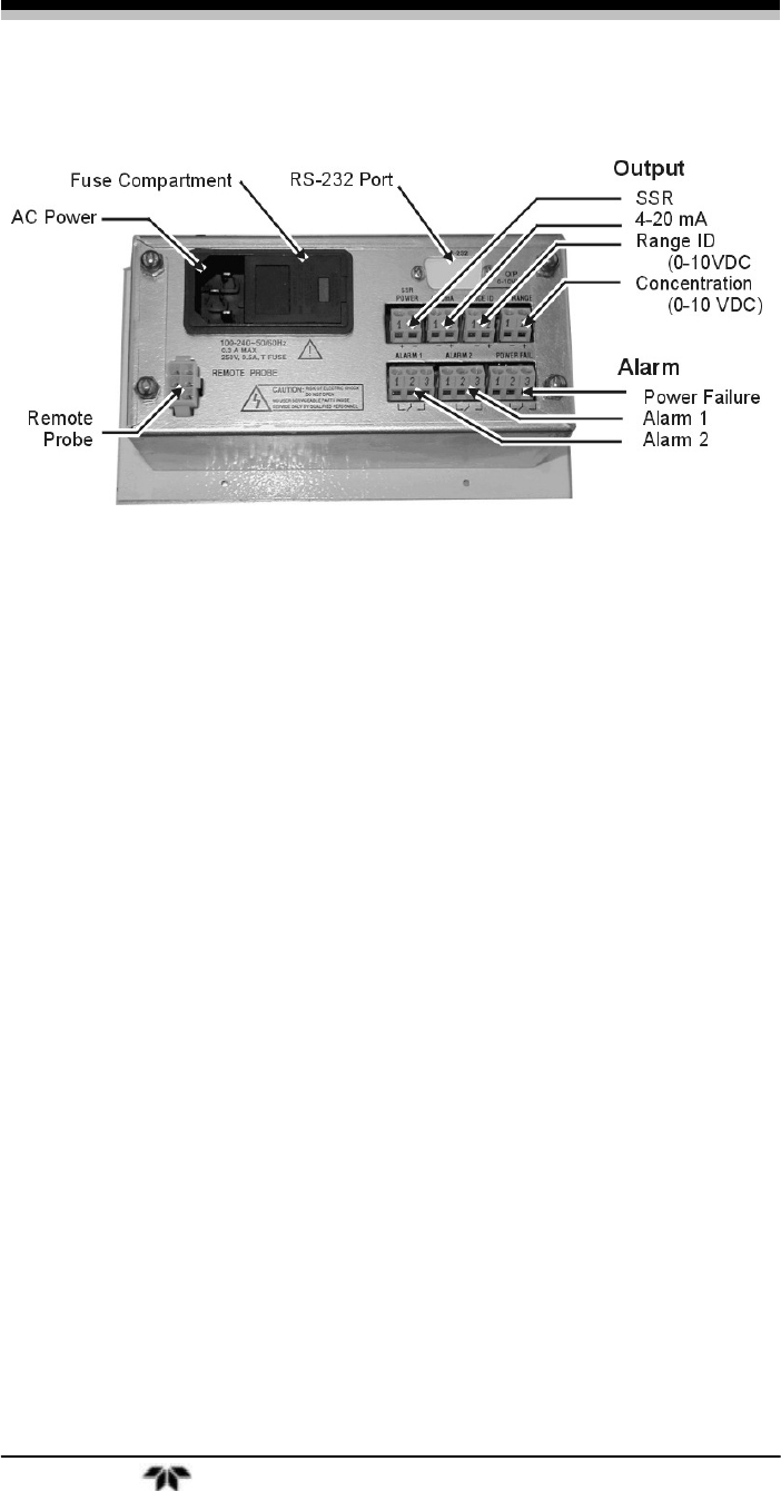
Figure 3-1: Electrical Connectors for AC Control Unit
3.3.1 Primary Input Power
A detachable power cord is installed directly into the Control Unit
and connects to a three pin terminal block on the rear panel. The
terminal block is provided for customer AC wiring.
The universal power supply allows direct connection to any 100-240 VAC,
50/60Hz power source. The fuse block, to the right of the power cord
receptacle, accepts two 5x20mm 0.5 A, 250V, IEC time-lag (T) fuse.
(See Fuse Replacement in chapter 5, Maintenance.)
For DC powered units, the customers DC power wiring is attached
to the two pin terminal block located on the rear of the control unit. See
Figure 1-3.
3.3.2 Analog Outputs
There are three DC (four on AC units) output signal connectors
with screw terminals on the panel. There are two wires per output with
the polarity noted. See Figure 3-1. The outputs are:
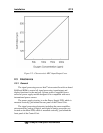
• 0–10 V % Range: Voltage rises with increasing oxygen
concentration, from 0 V at 0 percent oxygen to 10 V at full
scale percent oxygen. (Full scale = 100% of programmed
range.)
• 0–10 V Range ID: 3.33 V = Low Range, 6.66 V = High
Range, 10 V = Air Cal Range.


