


Operation AX300-I
Teledyne Analytical Instruments 22
1. Remove the batteries and remove the five screws that hold the
case together.
2. Remove the rear case section leaving the PCB in the front half of
the case.
3. Remove jumper at position JP3 and reinstall it at position JP7.
4. Replace the rear cover and secure in place with five screws.
Install the batteries and recalibrate per Section 2.1.3.
CAUTION: RECORDER/RS232 OUTPUT SIGNAL SHOULD ONLY
BE CONNECTED TO AN EN60601-1/IEC60606-1
APPROVED DEVICE.
To reconfigure the analyzer from a digital (RS 232) output to
analog (0-1 VDC) output, use the same procedure except in step 3
remove the jumper from JP7 and replace it at JP3.
2.2 Use
2.2.1 Procedure
Note: Prior to use, always test the batteries. Also check
calibration, the sensor for leaks and damage, and the
alarm settings.
The AX300-I instrument can be used to measure a gas mixture for
oxygen in two basic modes:
• In the inhalation side of breathing circuit ahead of
antibacterial filters, humidifiers and medicating devices or
other instances where gases are flowing to a patient in
breathing circuits.
• In confined volumes such as incubators or tents.
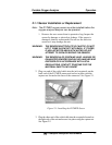
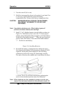
When analyzing for oxygen in breathing circuits, the flow diverter
must be used. The diverter should be screwed onto the threaded front
end of the R17MED sensor. A tee adapter (plastic, P/N A268, or metal,
P/N A283) should be placed into the circuit, and the above sensor
assembly plugged into the tee adapter. See Figure 2-3.
CAUTION: CHECK THE BREATHING CIRCUIT FOR LEAKS. BE
CERTAIN THAT THE CIRCUIT DOWNSTREAM OF
THE SENSOR DOES NOT PRODUCE ANY