


930578 Rev. B
IX. Set-Up, Adjustment & Use
33
2. Angle-Adjustment
a. Loosen bolt.
b. Set armrest at desired angle using preset holes
in armrest angle (A) plate.
c. Tighten bolt.
L. SEAT DEPTH
The solid back has an adjustment range of 6".
1. Adjustment
a. Remove the two bolts securing the backrest pivot
onto the seat frame.
b. Position the backrest pivot plate in the
pre-drilled holes on the frame.
c. Replace bolts and tighten securely.
NOTE– This adjustment may also require repositioning
the seat-to-back bracket (underneath the solid
seat) into the second set of mounting holes.
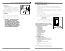
M. TILT-IN-SPACE MECHANISM
The tilt-in-space mechanism is installed at Sunrise.
A cable trigger mechanism positively locks in place
from 90° to 145°.
1. Adjustment
a. Loosen jam by turning it clockwise.
b. Turn the cable adjuster piece until looseness is
removed from cable.
c. Tighten jam nut.
NOTE– With 15" and 16" frames two tilt-in-space
mechanisms are required.
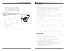
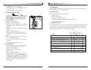
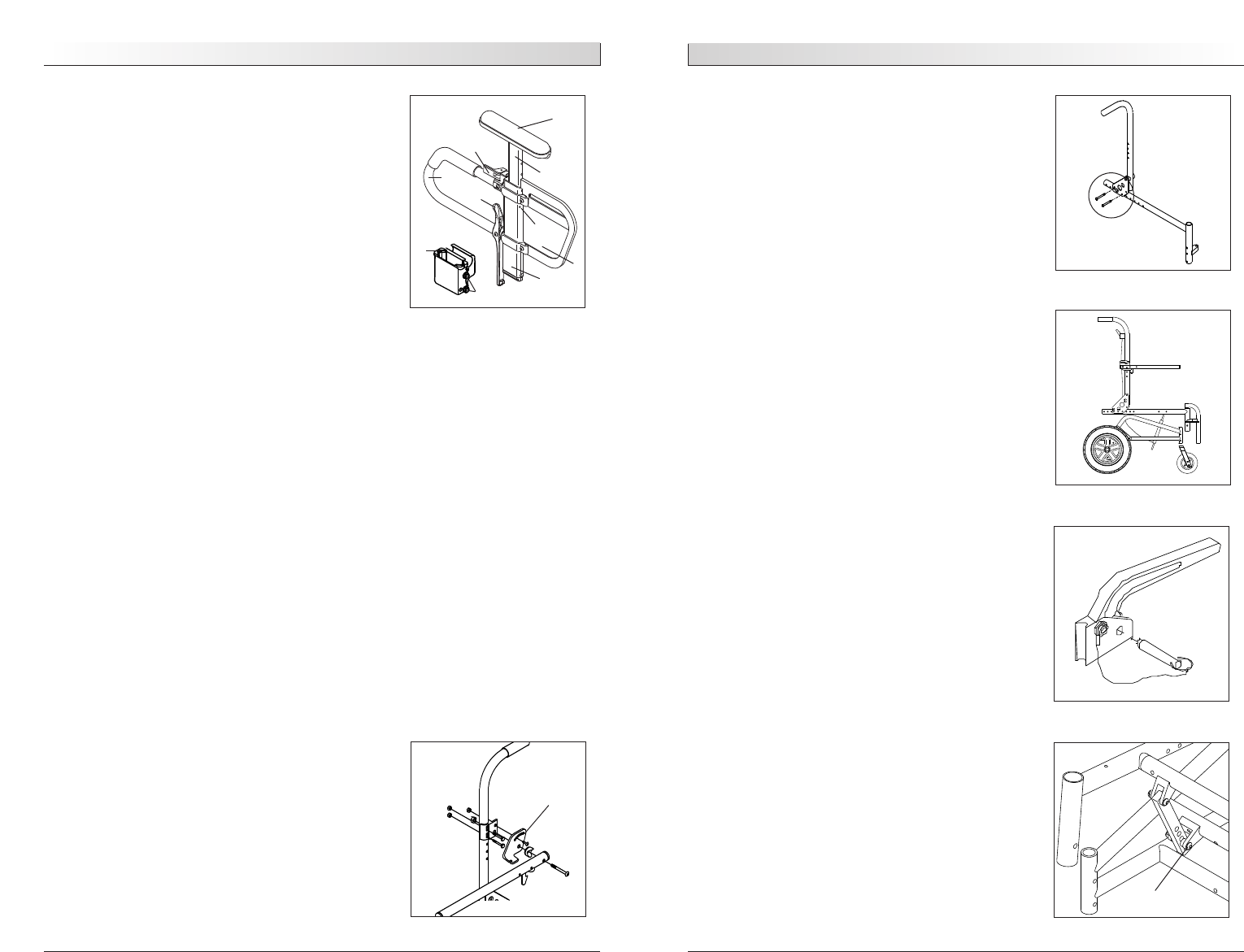
N. NONTILT
A 15" angle-adjustment is standard on all
Quickie Z-500 wheelchairs with a nontilt option.
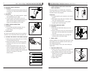
1. Nontilt Bracket Adjustment
a. Remove the lower securing bolt (A) on the
nontilt bracket.
b. Set at desired angle. There are five holes
(in 3" increments) to choose from.
c. Reinstall the bolt and tighten securely.
IMPORTANT NOTE– Do not position the front seat
height lower than the rear.
IX. Set-Up, Adjustment & Use
930578 Rev. B
32
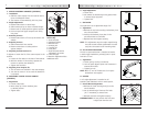
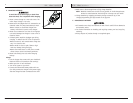
J. HEIGHT-ADJUSTABLE ARMRESTS (OPTIONAL)
1. Installation
a. Slide the outer armpost into the receiver mount-
ed to the wheelchair frame.
b. The armrest will automatically lock into place.
2. Height Adjustment
a. Rotate release lever to second stop.
b. Slide armrest pad up or down to desired height.
c. Return lever to locked position against armpost.
d. Push arm pad until upper armpost locks firmly
into place.
3. Removing Armrest
a. Rotate release lever to first stop and remove the
armrest.
4. Replacing Armrest
a. Slide armrest back into receiver.
b. Return release lever to locked position
against armpost.
5. Adjusting Armrest Receiver Fit
To tighten or loosen the fit of the outer armpost in the
receiver:
a. Loosen the four bolts on the sides of the receiver.
b. With the armrest in the receiver, squeeze the
receiver to achieve the desired fit.
c. Tighten the four bolts.
6. Adjusting Inner Armpost Fit
a. Two set screws are installed in the outer armpost.
b. Turn the set screws in or out until the desired fit
is achieved.
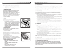
K. ADJUSTABLE LOCKING FLIP-UP ARMREST
(OPTIONAL)
1. Adjustment
a. Loosen clamp bolts.
b. Move clamp up or down backrest posts
to desired position.
c. Tighten bolts.
A
A
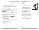
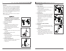
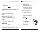
Height-Adjustable
Armrest Key
1. Outer armpost
2. Standard receiver
3. Release lever
4. Armrest pad
5. Transfer bar
6. Side panel
7. Outer armpost tension
adjustment set screws
8. Inner armpost
9. Receiver adjustment bolts
10.Release Lever
1
10
6
7
8
4
3
5
2
9