


26
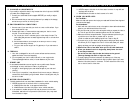
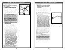
IX. SET UP & ADJUSTMENT
I. WHEEL LOCKS
Note: Use a torque setting of 100 in.-lbs. when
setting up wheel locks.
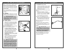
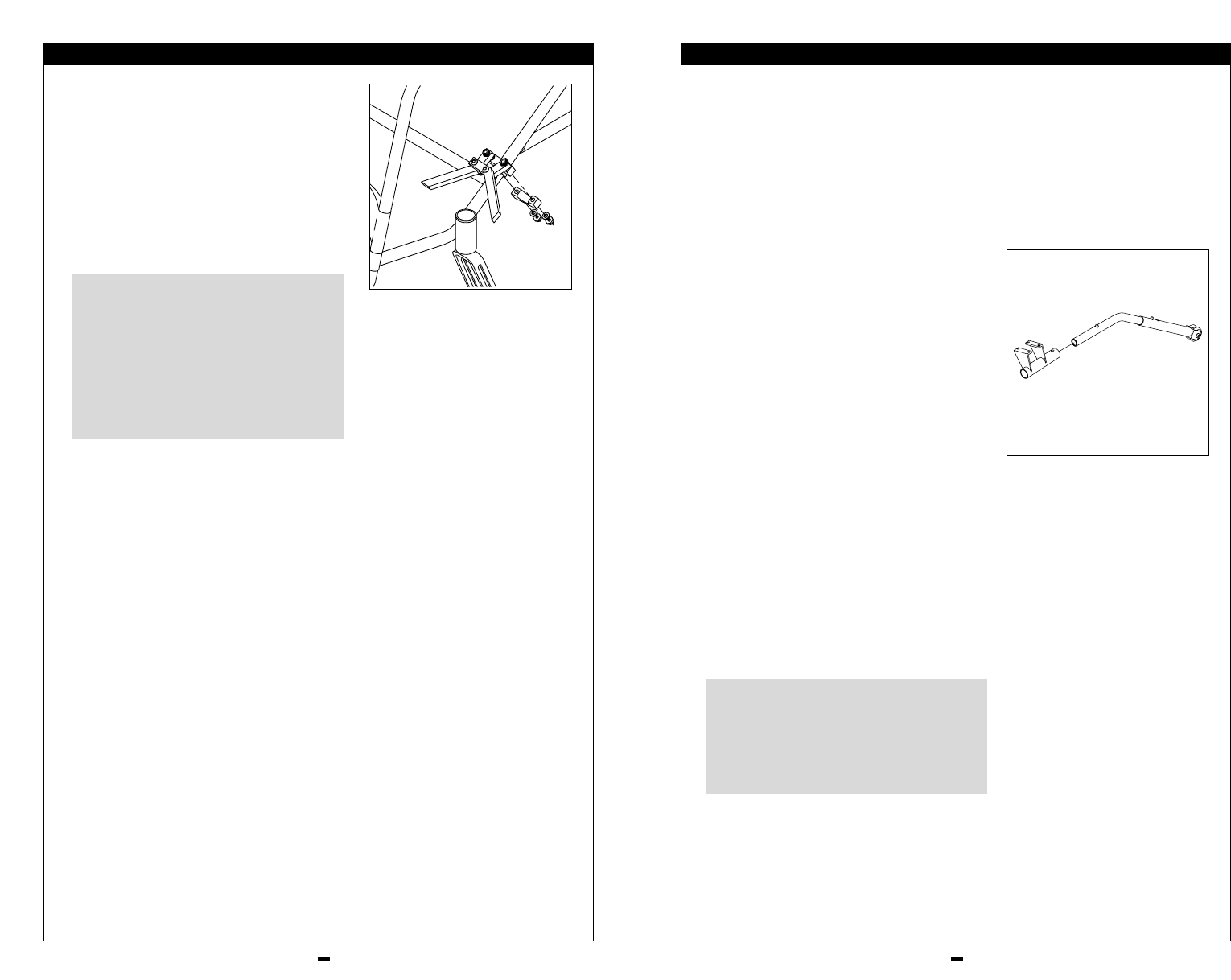
1. Low-Mount Scissor Wheel Locks:
Loosen screws on top clamp. Slide
assembly toward rear wheel until clamp
embeds into tire to prevent wheel move-
ment, when in locked position. Adjust
angle position and tighten screws.
Using wheel locks for braking is danger-
ous. Use wheel locks for parking ONLY.
When properly adjusted, wheel locks pre-
vent the rear wheels from turning when
the chair is parked. Always adjust the
wheel locks after making any changes to
the rear axle sleeve position. Wheel locks
should be embedded into the tires to pre-
vent wheel movement.
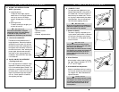
2. High-Mount Push-to-Lock or Pull-to-
Lock Wheel Locks:
To adjust push-to-lock toggle type locks that
mount with a split clamp, loosen the screws
on the top of each clamp. Using a 3/16”
Allen wrench, turn one of the screws coun-
terclockwise one-quarter turn. Repeat the
same process with the second of the two
screws. Alternately loosen the screws (two
turns each) until both screws are removed.
Slide clamp toward the rear wheel until the
wheel lock is embedded into the tire to
prevent wheel movement (when in the
locked position). Tighten screws. Some
adjustments to the wheel lock position can
be accomplished without moving the clamp.
To adjust, loosen the two socket-head cap
screws on the top of the clamp. Slide the
mounting bar forward or backward and
rotate it to the correct angle position. The
wheel lock should embed into the tire to
prevent wheel movement when in the
locked position. Tighten screws.
Note: High-mount push-to-lock require frame
modifications for use on your Shadow Rigid.
▲
!
WARNINGS
IX. SET UP & ADJUSTMENT
J. FOOTREST
Adjust height by removing bolts and sliding
footrest up or down to desired position.
Replace bolts.
Note: Footrest adjusts in 3/4” increments. Keep
footrest 1”-2” above the ground. Use a torque set-
ting of 100 in./lbs. when adjusting footplate.
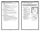
K. ANTI-TIP TUBES (Optional)
Note: Use a torque setting of 100 in.-lbs. when set-
ting up the anti-tip tubes.
Remove anti-tip tubes from anti-tip
receivers. Remove button head bolts from
camber tube mounting brackets. Install
anti-tip receiver on the underside of the
camber tube with the long part of the tube
facing rearward. Use the longer screw
supplied with the anti-tips and reinstall
the camber tube and mounting brackets.
Insert the anti-tip tube into the receiver.
Turn the anti-tip tube down until release
pin is through the receiver mounting hole.
Insert second anti-tip tube the same way.
CAUTION:To allow the anti-tip tubes to func-
tion properly there must be a 1 1/2” to 2”
clearance from the anti-tip wheel to the
ground. To maintain this clearance an adjust-
ment in the positioning of the anti-tip tube
should be made to correspond with any
change in seat height.
Failure to adjust anti-tip tubes correctly can
result in injury to the rider. Anti-tip tubes
are available from your local authorized
Quickie supplier. Quickie Designs recom-
mends anti-tip tubes for wheelchairs.
▲
!
WARNINGS
27