


930457 Rev. A
X. Set-Up & Adjustments
31
X. Set-Up & Adjustments
930457 Rev. A
30
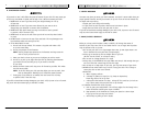
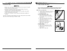
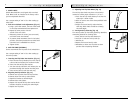
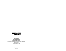
3. Adjusting Anti-Tip Tube Wheel (Fig. 15)
The anti-tip tube wheels may have to be raised or
lowered to achieve proper clearance 1 1/2" to 2".
a. Press the anti-tip wheel release pin so that the
release pin is drawn inside.
b. Raise or lower to one of the three predrilled holes.
c. Release pin.
d. Adjust the second anti-tip tube wheel the
same way. Both wheels should be at exactly
the same height.
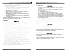
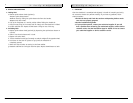
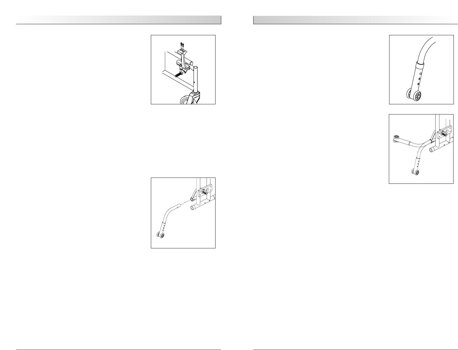
4. Turning Anti-Tip Tubes Up (Fig. 16)
Turn anti-tip tubes up when being pushed by attendant,
overcoming obstacles or climbing curbs.
a. Press the rear anti-tip tube release pin.
b. Hold pin in and turn anti-tip tube up.
c. Release pin.
d. Repeat with second anti-tip tube.
e. Remember to return anti-tip tubes to down
position after completing maneuver.
I. WHEEL LOCKS
Quickie M6 wheelchairs are shipped with two wheel
locks. Wheel locks are installed at the factory unless
you have requested otherwise.
Use a torque setting of 100 in.-lbs. when setting up
wheel locks.
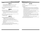
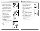
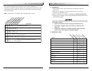
1. Push-to-Lock Wheel Locks Adjustment (Fig. 13)
a. Using a 3/16" Allen wrench, turn one of the screws
in the clamp counterclockwise one-quarter turn.
b. Repeat the same process with the
second of the two screws.
c. Alternately loosen the screws (two turns each)
until both screws are removed.
d. To prevent wheel movement when in the locked
position, slide clamp toward the rear wheel until
the wheel lock is embedded into the tire.
e. Tighten screws.
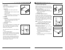
J. ANTI-TIP TUBES (OPTIONAL)
Sunrise recommends anti-tip tubes for all wheelchairs.
Use a torque setting of 100 in.-lbs. when setting up
the anti-tip tubes.
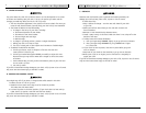
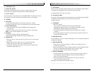
1. Inserting Anti-Tip Tubes Into Receiver (Fig. 14)
a. Press the rear anti-tip release pins on the anti-tip
tube so that both release pins are drawn inside.
b. Insert into the anti-tip tube receiver.
c. Turn the anti-tip tube down until release pins are
positioned through the receiver mounting hole.
d. Insert second anti-tip tube the same way.
2. Adjusting Anti-Tip Receiver (Fig. 14)
a. Remove anti-tip tubes from anti-tip receivers.
b. Remove bolts from anti-tip tube receiver.
c. Reposition bracket to desired height.
d. Reinsert bolts and tighten.
e. Repeat with second anti-tip tube receiver. Both
brackets should be at exactly the same height.
f. Replace anti-tip tubes.
Figure 13
Figure 14
Figure 16
Figure 15