


930457 Rev. A
X. Set-Up & Adjustments
27
X. Set-Up & Adjustments
930457 Rev. A
26
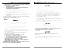
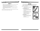
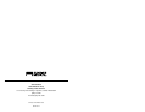
D. FIXED FRONT FOOTRESTS
1. Adjustment (Fig. 6)
a. Remove mounting bolts on the top of each
extension tube.
b. Make sure the inserts remain in place.
c. Slide footrest tube into front frame tube to
desired height.
d. Line up holes and replace the bolt on the outside
through frame, footrest and insert.
e. Follow same procedure on opposite side.
f. Align footrests to desired inward/outward rota-
tional position and tighten firmly.
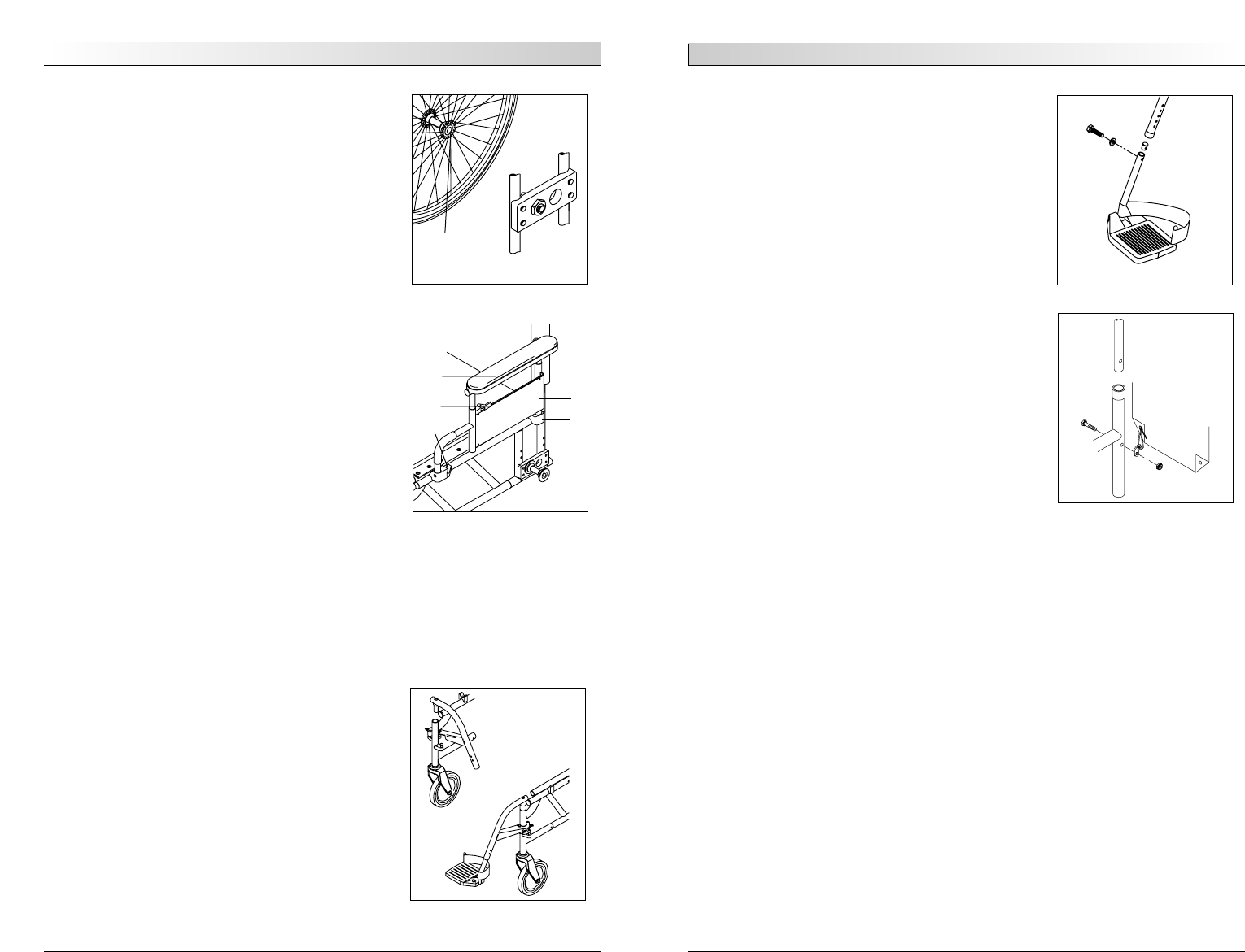
E. BACKREST
1. Height Adjustment (Fig. 7)
a. Remove the backrest upholstery from the frame.
b. You will see the backrest tube which telescopes
into the frame and is secured by a screw on the
side of the frame.
c. There are holes 1 1/8 inch apart from which you
may choose to set the back height.
d. Remove the two backrest bolts from the rear
frame tubes.
e. After selecting the proper height, insert bolt
through frame and backrest tube.
f. Attach upholstery tab to bolt and tighten nut
and bolt assembly.
g. Insert nylon tie through upholstery grommets.
Tighten and cut off excess nylon tie.
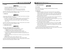
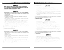
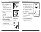
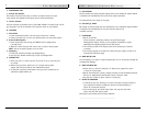
Removable Height-Adjustable
Armrest Key
1. Armrest Pad
2. Upper Securing Lever
3. Release Latch
4. Armrest Panel
5. Rear Receiver
1
2
4
5
3
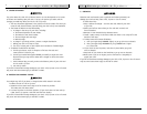
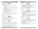
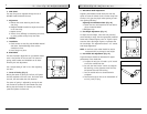
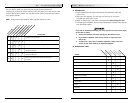
A. WHEELS
1. Installation
a. Depress the quick-release button on the
axle.(Fig. 3)
b. Slide through wheel hub and into axle sleeve
until it locks.
c. The axle is not secured until the outside
quick-release button pops out to its fully
extended position.
d. The ball bearing on the opposite end of the
axle must be fully visible beyond the end of
the axle sleeve.
B. REMOVABLE HEIGHT-ADJUSTABLE ARMRESTS
Height-adjustable armrests are installed at Sunrise.
1. Height Adjustment
a. Release the upper securing lever.
b. Slide armpad up or down to
desired height.
c. Return lever to locked position.
2. Removing Armrest
a. Depress the release latch, and lift the armrest up.
b. To return armrest to operating position, drop
armrest into receiver, and pull lever back. Make
sure the armrest is locked in place.
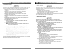
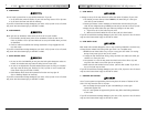
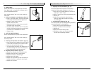
C. SWING-AWAY HANGERS AND
FOOTRESTS (60º, 70º, 70ºV OR 90º)
1. Installation (Fig. 5)
a. Place swing-away pivot saddle into the receiver
on front frame tube with the footrest facing out-
ward from the frame. (Fig. 5-A)
b. Rotate the footrest inward until it locks into
place on locking bolt. (Fig. 5-B)
2. Removal
a. To remove footrest, push release latch toward the
frame.
b. Rotate footrest outward and lift.
Quick-Release
Button
Figure 3
Figure 5
A
B
Figure 7
Figure 6