


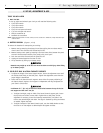
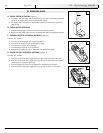
H. BACKREST ANGLE ADJUSTMENT (Figure 8)
A backrest angle adjustment is standard.
Adjustment on Seat Frame
1. Remove the front securing bolt (A) on the side of the backrest hinge plate.
2. Loosen the lower rear bolt (B).
3. Set at desired angle. There are four holes (in 4º increments) to choose from.
4. Reinstall the front bolt and tighten both bolts securely.
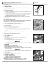
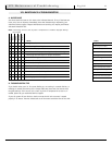
I. SEAT HEIGHT ADJUSTMENT (Figures 9 & 10)
The seat height can be adjusted from 17.5" - 21.5" (M11) and 19" - 23" (F11) at
1" increments.
1. Remove the seat.
2. Reposition all four of the seat mounts (C) to desired position by removing pins (D),
adjusting mounts and replacing pins.
3. Ensure that the top of all seat mounts sit at the same height (except as noted
below).
4. Replace seat.
NOTE– 1" of seat angle can be set by lowering the rear post two hole positions.
In all configurations of seat height and fixed tilt angles, ensure that both the
front and rear latches (2) are all properly engaged.
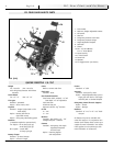
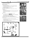
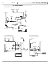
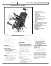
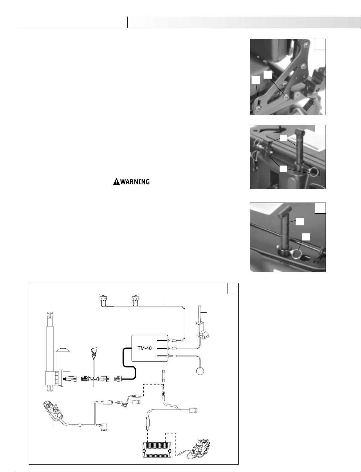
J. TM40 SINGLE OR DUAL SWITCH ACTUATOR CONTROLLER (Figure 11)
The TM40 actuator controller can be used to activate the tilt mechanism with either single
or dual switch controls.
1. Plug limit switch harness assembly (1) into TM40 limit switch jack (2).
2. Plug single switch (3) into TM40 single switch jack (4) OR plug dual switch (5) into
TM40 dual switch jack (6).
3. Plug TM40 into the QTRONIX Power Module (7).
4. Use mating plugs (8) to connect the TM40 to the tilt actuator.
930584 Rev. A
8
English
V. Set-up, Adjustment & Use
5
1
4
6
2
DRIVE INHIBIT
SWITCH
TILT STOP
SWITCH
DUAL
SWITCH
UPRIGHT STOP
SWITCH
9-PIN
CONNECT
TO ONBOARD
CHARGER
TILT ACTUATOR
SINGLE
SWITCH
VSI CONTROLLER
QTRONIX POWER MODULE
8
7
C
D
Front Mounts
Rear Mounts
OR
9
10
11
8
A
B
C
D
3