


930584 Rev. A
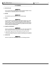
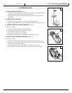
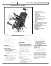
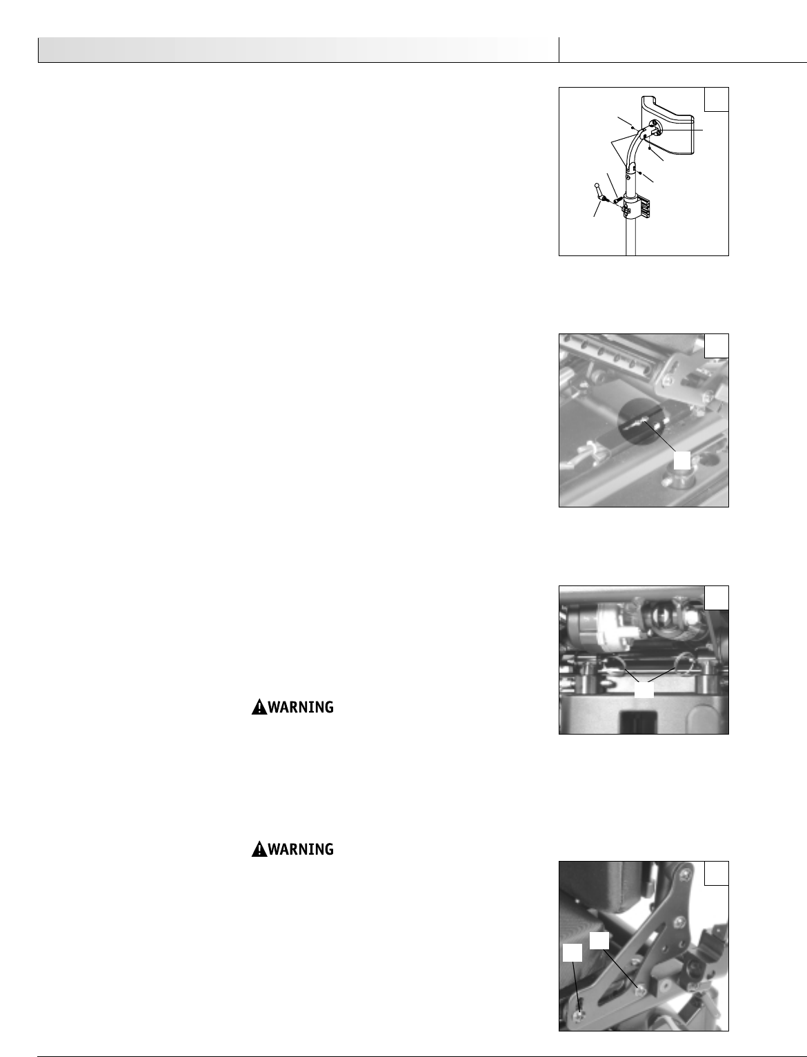
C. HEADREST (Figure 4)
1. Mounting a Headrest.
The Solid Seat Back has a headrest plate mounted to it. Care should be taken to use the
proper screw length when mounting.
2. Positioning the Headrest
a. To position the headrest use the double clamp and the collar clamp (B,C,D) to obtain
the proper height and distance.
b. For clamp B use a 3/32 Allen set screw (A) and a 3/16 Allen cap screw. Clamp B posi-
tions the headrest forward and aft. However, due to the vertical movement of this
adjustment, collar clamp D will have to be moved in conjunction.
c. Retighten both the 3/16 Allen and the set screws (A) with a 3/32 Allen wrench.
D. FOAM BACK
Secure the foam and cover to the shell.
To secure the back foam and cover on the Solid Seat Back, slide the top edge of the cover
over the top lip of the shell. Press the back in place against the shell.
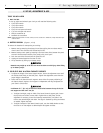
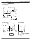
E. SEAT TILT ADJUSTMENTS & DRIVE LOCK-OUT (Figure 5)
1. Maximum Tilt Angle
Maximum tilt angle can be adjusted to a limit of 50°.
a. Loosen and remove switch fasteners (E).
b. The switch can be positioned foward and aft within slot in order to fine tune the
maximum tilt angle. Foward postions increase tilt angles. Aft position remove tilt
angles.
c. Tighten the switch fasteners at desired maximum tilt angle
2. Drive Lock out Angle
The Drive Lock-out angle is fixed and is set at 15°±3°
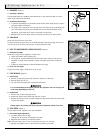
F. SEAT REMOVAL (Figure 6)
1. Remove Seat
a. Removal is most easily done when the seat is tilted at or above 40°.
b. Remove safety lock pin (F).
c. Flip seat back and remove with a slight forward motion.
It is recommended that two people perform this operation. The seat is heavy and
can be large depending on seat size.
2. Replace Seat
a. Position rear of seat on docking mount.
b. Rotate seat forward until latches lock the seat in place.
c. Replace the safety lock pin (F) under release lever and position both rear latch knobs
outward and tighten.
Always replace the latching lock pins to prevent inadvertent release of the seat.
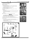
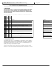
G. SEAT DEPTH (Figure 7)
The seat depth can be adjusted in one inch increments.
1. Seat Frame Depth Adjustment
a. To adjust, remove the two bolts
(G & H) from each side of the backrest pivot plate.
b. Reposition the backrest to the desired position.
NOTE– Substitute Bolt (H) with rear back rest pivot plate bolt (G) for 18" seat depth.
c. Replace and retighten bolts on each side of the backrest pivot plate.
V. Set-up, Adjustment & Use
7
English
A
A
A
B
B
C
D
4
5
6
7
F
E
G
H