


Jazzy Sport 2 www.pridemobility.com 9
III. YOUR POWER CHAIR
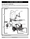
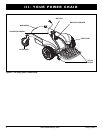
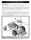
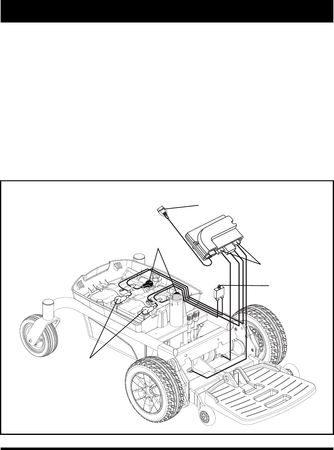
Figure 3. Jazzy Sport 2 Electrical Components
Electrical Components
The electrical components are located either on or inside the power base. The main circuit breaker is located on
the front of the power base. The power module is located under the front cover. See figure 3.
Main Circuit Breaker: The main circuit breaker is a safety feature built into your power chair. When the batteries
and the motors are heavily strained (e.g., from excessive loads), the main circuit breaker trips to prevent damage
to the motors and the electronics. If the circuit trips, allow your power chair to “rest” for approximately one
minute. Next, push in the circuit breaker button, turn on the controller, and continue normal operation. If the main
circuit breaker continues to trip repeatedly, contact your authorized Pride Provider.
Power Module: Provides connection between the controller and the motors and batteries.
The GC3 control system supplied with your power chair has been factory set to operate within safe limits for
speed, acceleration, deceleration, dynamic stability, and braking. The system is not programmable. Contact your
authorized Pride Provider with any questions regarding the operation of your power chair. All components, their
connections, and function are identical to the information supplied in the controller basic operating instruction
provided with your power chair. See figure 3.
CONTROLLER HARNESS
MOTOR CONNECTORS
MAIN CIRCUIT BREAKER
BATTERY CONNECTORS
BATTERY CONNECTORS