


17
Outlander Series www.pridemobility.com
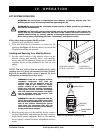
Follow these steps to remove a mobility device from
the lift system:
1. Lower the lift platform to the ground.
2. Unfasten the tie-down straps or allow the lock-down
arm to automatically return to the vertical position.
Unlock and loosen the tie-down straps.
Rotate the adjustment lever only on each strap
forward and rearward in a ratcheting motion
until each strap reaches its original furled
position.
3. Unload the mobility device from the lift platform.
WARNING! Do not attempt to manually
pull the lift platform down from the
stowed position. Doing so will result in
product damage and will void the prod-
uct warranty.
4. Raise the lift platform for storage, noting that it will
automatically fold into a stowed position.
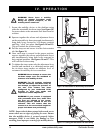
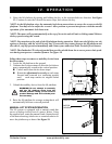
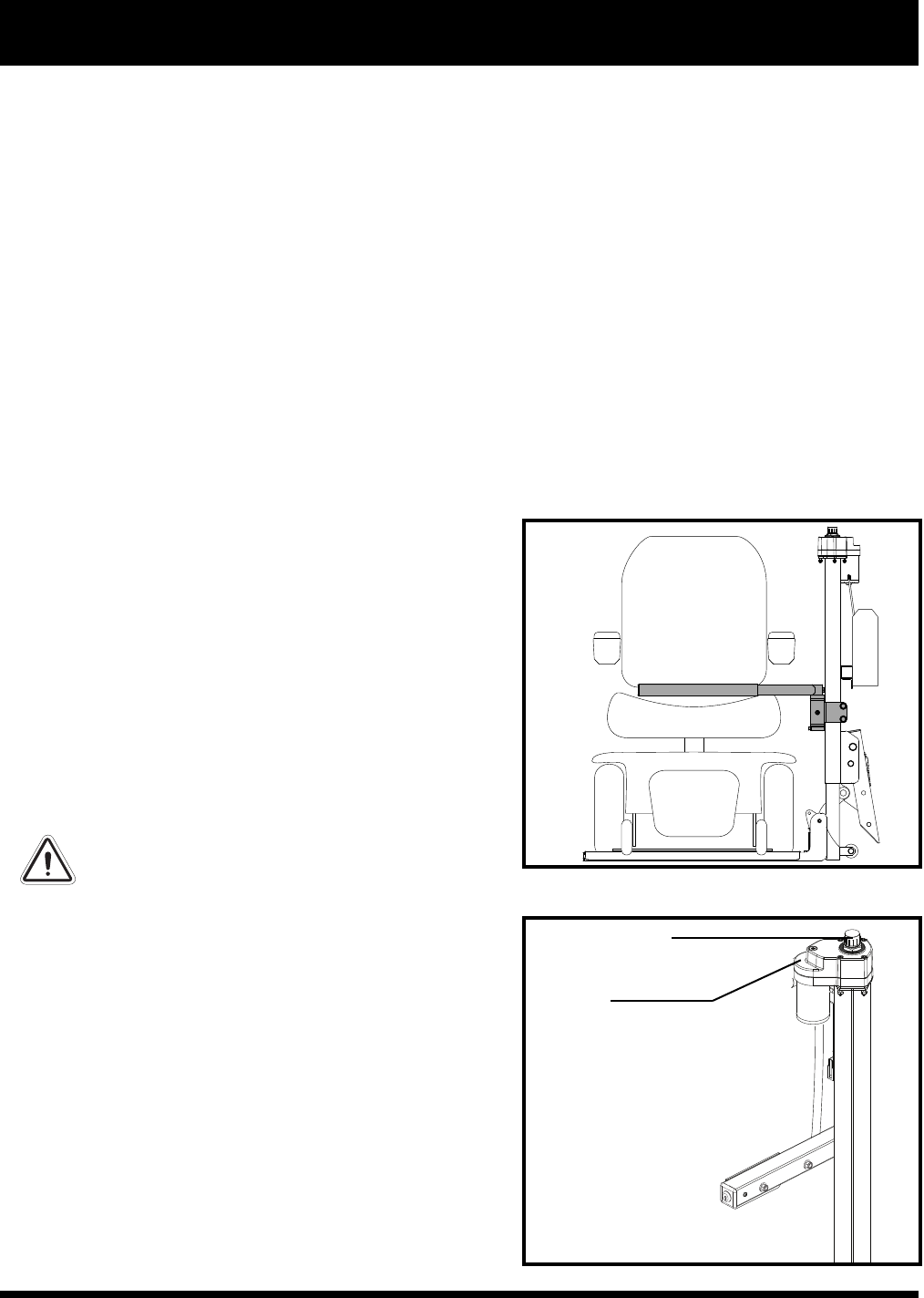
MANUAL LIFT SYSTEM OPERATION
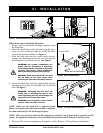
The lift system is equipped with a manual crank that
serves as backup in the event of a power failure. Using
the supplied tool, rotate the manual crank (located on top
of the motor housing) clockwise or counterclockwise to
move the platform up or down. See figure 19.
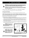
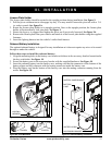
4. Raise the lift platform by turning and holding the key in the counterclockwise direction. See figure
13. Continue to raise the lift until the motor stops, then release the key.
NOTE: As the lift platform rises, the automatic lock-down arm activates to secure the scooter to the lift
platform. You may need to adjust the scooter’s tiller position to prevent interference with the smooth
operation of the automatic lock-down arm.
NOTE: The motor will stop automatically at the top of its stroke and will emit a clicking sound. Release
the key upon hearing this sound.
NOTE: Pay attention to the path of the lift platform during operation. Make sure the lift does not rub
against or interfere with the vehicle in any way. If you notice any contact between the lift platform and
the vehicle, stop lift operation immediately and contact your authorized Pride Provider for assistance.
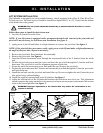
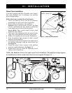
NOTE: The Outlander LP is the only model that provides a hold-down bar to secure power chair prod-
ucts during transport as a standard feature. See figure 18.
IV. OPERATION
MANUAL CRANK
MOTOR
HOUSING
Figure 19. Manual Crank Operation
Figure 18. Power Chair Hold-down Bar