


11
Outlander Series www.pridemobility.com
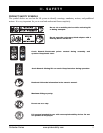
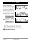
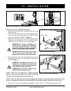
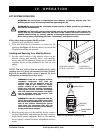
TENSION
BOLT
CLEVIS
PIN
III. INSTALLATION
Follow these steps to install the lift system:
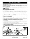
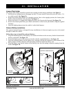
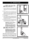
1. Remove the preassembled mounting hardware from
the hitch tube.
2. Mount the hitch tube to the lift frame using the previ-
ously removed mounting hardware. Install the hard-
ware in the direction indicated in figure 6.
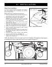
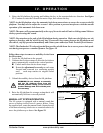
3. Slide the hitch tube into the vehicle hitch receiver,
aligning the mounting hole closest to the lift with the
mounting hole in the hitch receiver. See figure 7.
WARNING! Lift system components are
heavy. Ask for assistance if necessary
when attaching the lift frame to the hitch
receiver. Use proper lifting techniques
and avoid lifting beyond your capacity.
WARNING! Avoid pinch points! Do not hold
the lift frame by the pivot points when
mounting the lift frame to the hitch receiver.
4. Secure the hitch tube with the supplied bolt and nut,
inserting the bolt from the threaded side of the hitch
tube. See figure 7.
WARNING! Threading the bolt from the
wrong side or allowing the bolt to turn
while tightening the nut will dislodge the
threaded insert in the hitch tube.
WARNING! Do not attach a Class II hitch
tube to a Class III hitch receiver.
NOTE: Make sure the hitch bolt is tightened firmly
before securing the nut to the hitch assembly to minimize
the chance that the lift will tilt during transport.
Figure 6. Hitch Tube Assembly
Figure 7. Lift Frame Vehicle Mounting
HITCH TUBE
LIFT FRAME
HITCH RECEIVER
MOUNTING HARDWARE
NOTE: Make sure the hitch tube and lift platform are parallel to the ground before operating the lift
system. An angled hitch tube may cause unreliable lift operation and/or damage to the lift system.
5. Route the lift system wiring harness through the vehicle. Refer to “Wiring Harness Installation.”
Figure 5. Tension Bolt and Clevis Pin Adjustment