17
Mini Crosser www.pridemobility.com
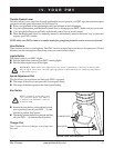
Throttle Control Lever
This lever allows you to control the forward speed and the reverse speed of your PMV up to the maximum speed
you preset with the speed adjustment dial. See figure 5A.
! Place your right hand on the right handgrip and your left hand on the left handgrip.
! Use your right thumb to push the throttle control lever to disengage your PMV’s brakes and move rearward.
! Use your right forefingers to pull back on the throttle control lever to move forward.
! When the throttle control lever is completely released, it automatically returns to the center “stop” position and
engages your PMV’s brakes.
NOTE: Allow your PMV to come to a complete stop before going from forward to reverse or reverse to forward.
Horn Buttons
These buttons activate a warning horn. The PMV must be powered up for the horn to be operational. Do not
hesitate to use the warning horn when doing so may prevent accident or injury.
Lights Button
This button controls your PMV’s lights.
! Push the light button to turn on your PMV’s running lights.
! Push the button again to turn off the lights.
WARNING! PMV users are required to use their lights when visibility is restricted—
day or night. Failure to use the lighting system in periods of poor visibility may result
in personal injury.
Speed Adjustment Dial
This dial allows you to preselect and limit your PMV’s top speed.
! The image of the tortoise represents the slowest speed setting.
! The image of the hare represents the fastest speed setting.
IV. YOUR PMV
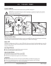
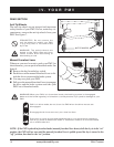
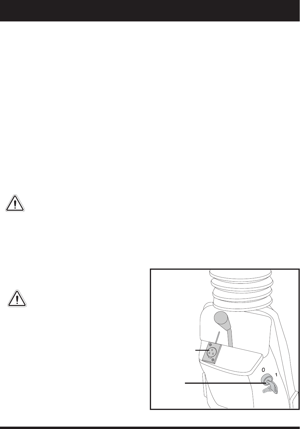
Key Switch
NOTE: If the key is moved to the
“off” position while your PMV is
in motion, the PMV will come to
a normal stop.
! Insert the key into the key switch and turn it clock-
wise to power up (turn on) your PMV — (1) indi-
cates the on position. See figure 6.
! Turn the key counterclockwise to power down (turn
off) your PMV — (0) indicates the off position.
Charger Port
The (3-pin) off-board charger cord plugs into
this port.
CHARGER PORT
KEY SWITCH
Figure 6. Lower Tiller Components


