


16 www.pridemobility.com Jet 2 HD
III. YOUR POWER CHAIR
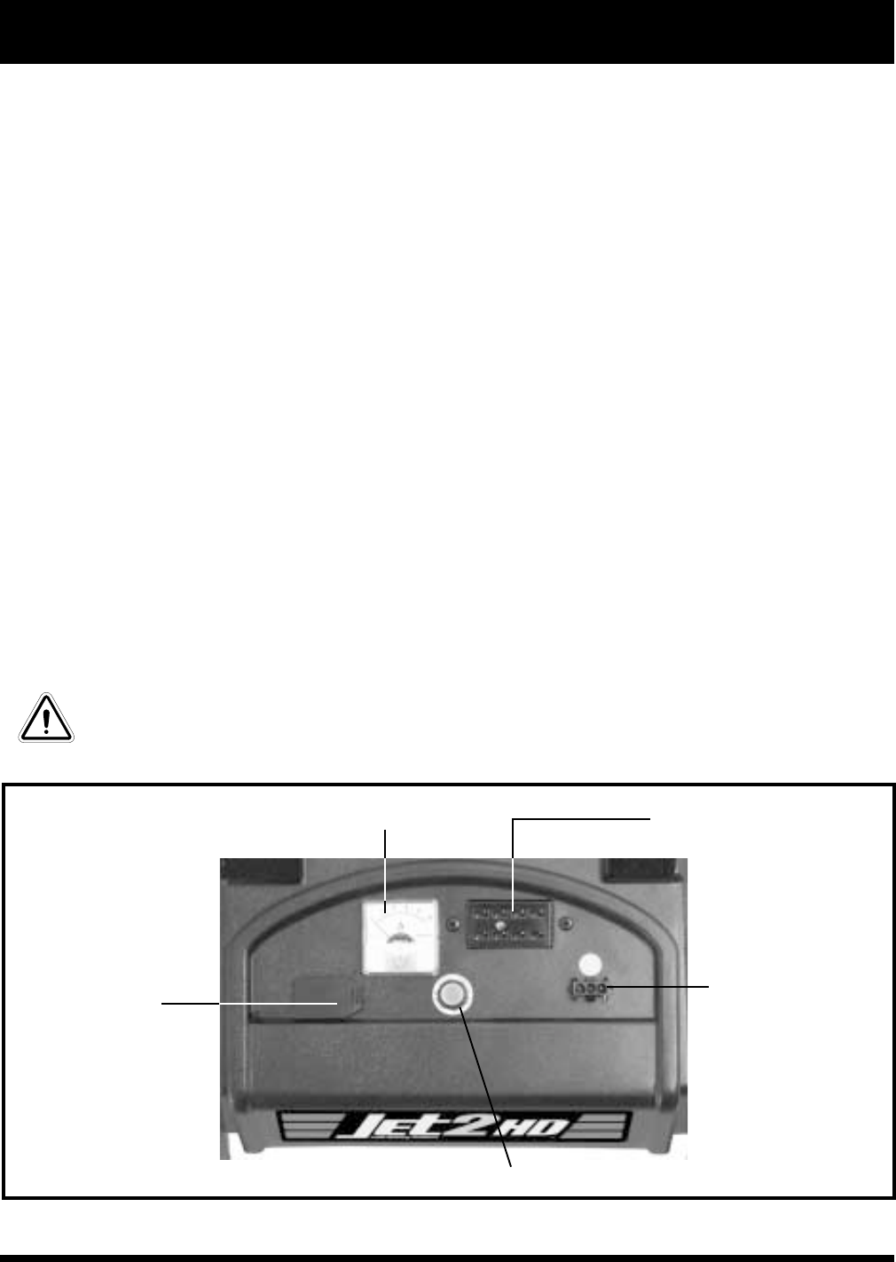
ELECTRONICS TRAY
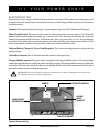
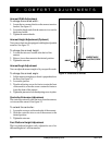
The electronics tray is located on the back of the power base. See figure 8. The ammeter, the charger power cord
receptacle, the main circuit breaker, the controller connector, and the charger inhibit connector are all located on
the electronics tray.
Ammeter: The ammeter displays the charger’s current output in amps. See VIII. “Batteries and Charging.”
Main Circuit Breaker: The main circuit breaker is a safety feature built into your power chair.. When the
batteries and the motors are heavily strained (e.g., from excessive loads), the main circuit breaker trips to prevent
damage to the motors and the electronics. If the circuit trips, allow your power chair to “rest” for approximately
one minute. Next, push in the circuit breaker button, turn on the controller, and continue normal operation. If the
main circuit breaker continues to trip repeatedly, contact your authorized Pride Provider.
Onboard Battery Charger AC Power Cord Receptacle: This is where the charger power cord plugs into the
onboard charger.
Controller Connector: This is where the controller connects to the power base.
Charger Inhibit Connector: Your power chair is equipped with a charger inhibit connector. The charger inhibit
enables the onboard charger to disable the controller during charging. The charger inhibit connector is coded with
colored dots. The dots are positioned so that you can align the flat side of the male connector with the flat side of
the female connector before making the connection.
WARNING! Failure to properly align the connectors can result in damage to the controller,
the charger harness, and the connectors.
Figure 6. Electronics Tray
AMMETER CONTROLLER CONNECTOR
CHARGER POWER
CORD RECEPTACLE
MAIN CIRCUIT BREAKER
CHARGER
INHIBIT
CONNECTOR