


20 www.pridemobility.com Jet 2/Rev F/Feb03
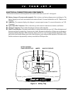
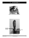
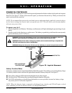
Figure 9. Charger Connector
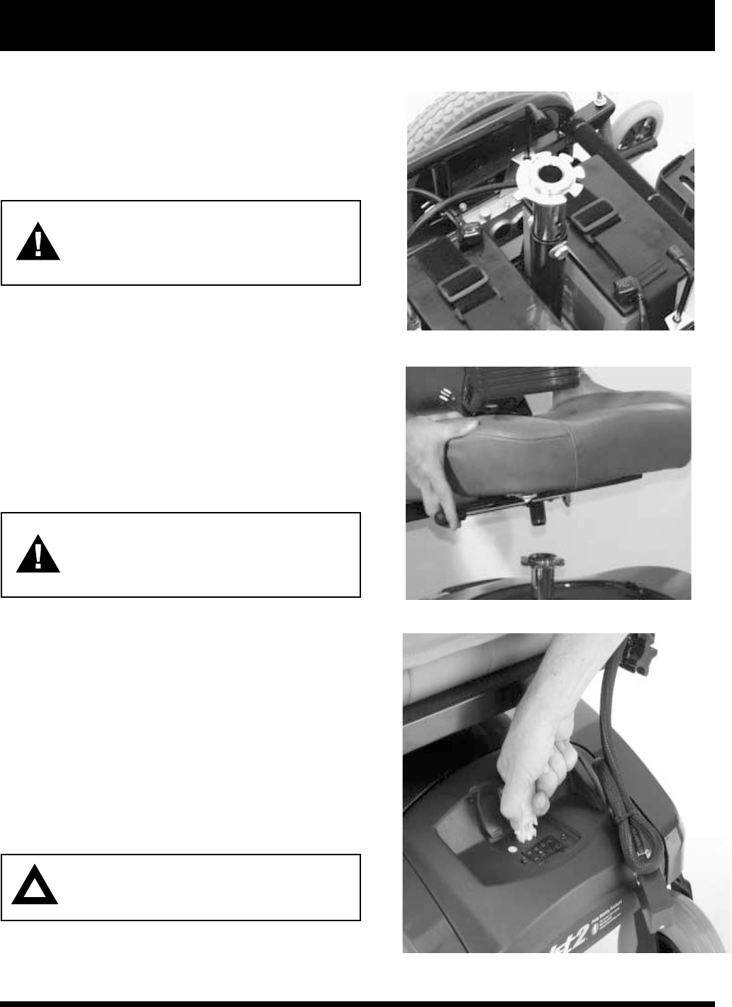
V. ASSEMBLY
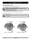
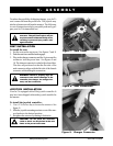
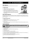
Figure 8. Seat Installation
Figure 7. Seat Tower
To reduce the possibility of shipping damage, your Jet 2s
seat is removed from the power base. The joystick may
also have been removed from the armrest. The following
is a set of instructions to help you quickly and easily pre-
pare your Jet 2 for immediate use.
WARNING! Do not pick up the seat by the
armrests. They are free to pivot, and you
may lose control of the seat if they do so,
resulting in personal injury and/or dam-
age to the chair.
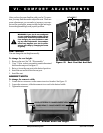
SEAT INSTALLATION
To install the seat:
1. Set the seat on the seat tower. See figures 7 and 8.
2. Push the seat down until the latch engages.
3. Plug in the charger connector and the 9-pin controller
connector into the power base. See figures 9 and
10. The charger connector is coded with colored dots.
The dots are positioned so that the flat side of the
male connector aligns with the flat side of the female
connector while making the connection.
WARNING! Failure to properly align the
connectors can result in damage to the
controller, the charger, the charger har-
ness, and the connectors.
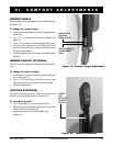
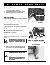
JOYSTICK INSTALLATION
Your Jet 2 is equipped with a Pilot joystick controller. It
may have been shipped without the joystick installed in
the armrest.
To install the joystick controller:
1. Use a 3/16-in. hex key to loosen the setscrew. See
figure 11.
2. Slide the joystick mounting arm into or out of the arm-
rest bracket to the desired position.
3. Retighten the setscrew by turning it clockwise.
CAUTION! Do not place the controller
cable so that it can be pinched in the seat
frame or the power base frame.