


Jazzy Select Series www.pridemobility.com 23
IV. ASSEMBLY
INITIAL ASSEMBLY
Your power chair may require some assembly either before initial use or after transportation.
NOTE: Any nylon insert lock nut removed during the disassembly or adjustment of the power chair must be
replaced with a new nylon insert lock nut. Nylon insert lock nuts should not be reused as it may cause damage
to the nylon insert, resulting in a less secure fit. Replacement nylon insert lock nuts are available at local
hardware stores or through your authorized Pride Provider.
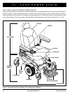
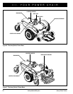
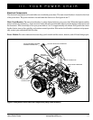
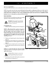
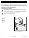
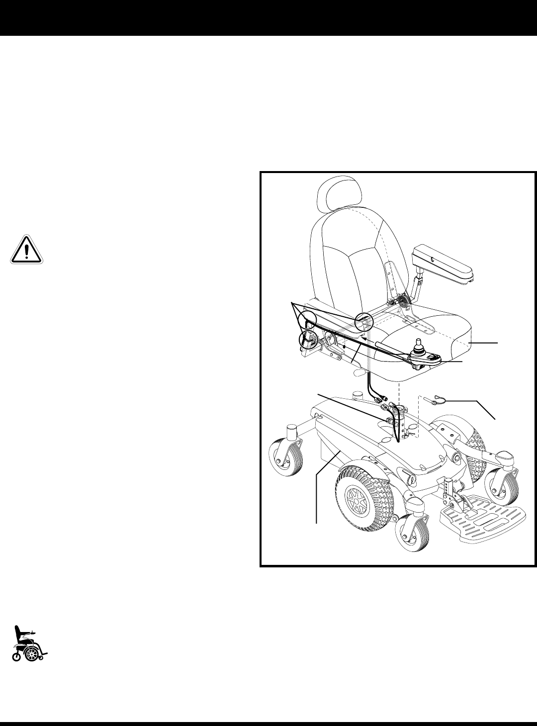
Figure 11. Seat and Controller Assembly
Seat Installation
It may be necessary to install the seat either prior to initial
operation or after transporting your power chair.
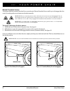
WARNING! Do not pick up the seat
frame by the armrests. They are free
to pivot, and you may lose control of
the seat if they do so.
To install the seat:
1. Slide the seat down onto the power base. See figure 11.
NOTE: The bottom hole on the seat post is
equipped with an internal welded pin, which sets
the seat height in the lowest position. If a seat
height other than the lowest position is desired,
you must install the supplied clevis pin into either
the middle hole or top hole on the seat post before
installing the seat.
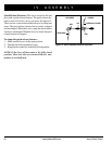
2. Tighten and clamp the quick-release fastener. See
figure 12.
3. Install the joystick module into one of the armrests.
Tighten the setscrew with the supplied hex key. See
figure 11.
4. Lift the armrest straight up, then route the joystick
module cable and secure with wire-ties as shown in
figure 11.
NOTE: It is important that the armrest be lifted
straight up prior to securing the joystick module
cable with wire-ties.
MANDATORY! Prevent controller
harness damage! Use correct tie-
down points for controller harness.
5. Plug the joystick module cable into the connector on
the power base. See figure 6 or 7.
SEAT
JOYSTICK
MODULE
CLEVIS PIN
POWER BASE
QUICK RELEASE
FASTENER
SETSCREW
WIRE TIES