


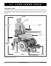
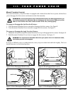

22 www.pridemobility.com Jazzy 1170XL
V. COMFORT ADJUSTMENTS
COMFORT ADJUSTMENTS
After becoming familiar with your power chairs operation, you may find the need to make some adjustments
to increase your comfort, such as seat height and angle, armrest angle, footrest height and angle, and the
controllers position. If your power chair is equipped with a Synergy or TRU-Balance Seating System, refer
to the information provided in separate manuals. If your power chair is equipped with a medium-back, a high-
back, or a reclining seat, refer to the following information.
WARNING! If your power chair was configured at your authorized Pride Provider, please
consult your healthcare professional before changing the seat position or making any
other adjustment. Some adjustments may degrade power chair performance and safety
by changing the center of gravity.
You may need the following to make comfort ad-
justments:
n metric/standard hex key set
n metric/standard socket set and ratchet
n adjustable wrench
Seat Height and Seat Angle Adjustment
The seat is attached to the power base through the
UMS. You can change the seat height by raising the
front and rear seat towers. If you raise or lower only
one set of towers (front or rear), you can also change
the seat base angle (dump).
To change the seat height:
1. Turn off the power to the controller and make sure
the unit is in drive mode.
2. Unplug the controller connector(s) from the elec-
tronics tray.
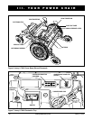
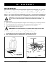
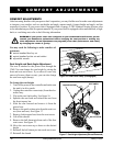
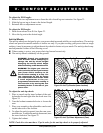
3. Flip up the seat latch safety. See figure 16.
4. Squeeze the seat latch and release the seat from
the front trapeze bar.
5. Slide the seat forward and remove it from the
power base.
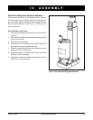
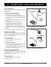
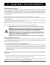
6. Remove the quick-release pins from the seat tow-
ers (front and rear). See figure 17.
7. Remove both trapeze bars from the seat towers.
8. Lift off the shroud
9. Remove the ball detent pin from each of the four
seat towers. See figure 17.
10. Move the seat towers up or down to the desired
height.
11. Reinstall the ball detent pin into each seat tower.
12. Reinstall the shroud.
Figure 16. Seat Latch Safety (Disengaged)
Figure 17. Seat Height Adjustment (Shroud Removed)
QUICK RELEASE PINS
SEAT TOWERS
BALL DETENT PIN